Generator Coupling
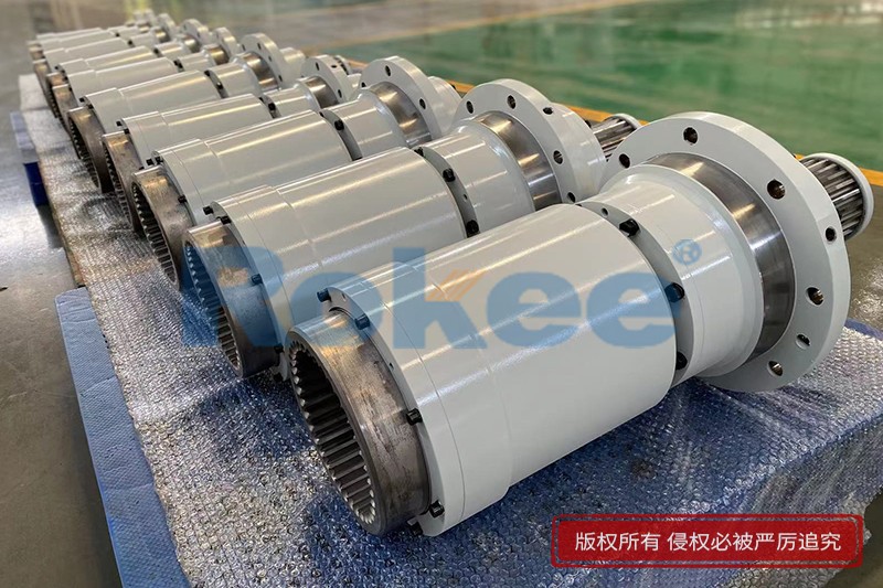
Rokee® is Generator Coupling Supplier from China, Support Customization and Export, due to excellent quality, complete technical services and superior cost performance, Rokee® Generator Coupling have been serving more than 60 countries and regions in the world, effectively operating in many corners of the world.
In the realm of power generation systems, the seamless transmission of mechanical energy from prime movers (such as turbines, diesel engines, or gas engines) to generators is paramount for ensuring stable and efficient electricity production. At the heart of this energy transfer process lies a critical component: the generator coupling. Serving as a mechanical bridge between the prime mover and the generator, the coupling not only transmits torque but also accommodates various misalignments, absorbs shocks and vibrations, and protects the connected machinery from potential damage.
1. Fundamental Principles of Generator Couplings
The primary function of a generator coupling is to establish a rigid or flexible connection between the output shaft of the prime mover and the input shaft of the generator, enabling the transfer of rotational torque while addressing inherent challenges in shaft alignment. In practical operation, perfect alignment between the two shafts is nearly impossible to achieve due to factors such as manufacturing tolerances, thermal expansion and contraction during operation, foundation settlement, and mechanical vibrations. The coupling must therefore be designed to accommodate three main types of misalignment: axial misalignment (relative movement along the shaft axis), radial misalignment (offset in the radial direction), and angular misalignment (tilt between the two shafts). Additionally, generators and prime movers often generate vibrations during operation; a well-designed coupling can absorb these vibrations to reduce noise and prevent excessive stress on the shaft bearings and other components.
Another key principle of generator couplings is torque transmission capacity. The coupling must be capable of transmitting the full torque output by the prime mover to the generator without slipping or failing. The torque capacity is determined by factors such as the material strength, dimensions of the coupling components (e.g., bolts, flanges, or flexible elements), and the type of connection (rigid or flexible). Moreover, couplings may also play a role in overload protection; some designs incorporate shear pins or friction elements that break or slip when the torque exceeds a predetermined limit, preventing damage to the generator, prime mover, or other downstream equipment.
2. Main Types of Generator Couplings
Generator couplings can be broadly classified into two main categories: rigid couplings and flexible couplings. Each type has distinct structural characteristics, advantages, and limitations, making them suitable for different application scenarios in power generation systems.
2.1 Rigid Couplings
Rigid couplings are designed to create a fixed connection between the two shafts, meaning they do not allow any relative movement or misalignment. As a result, they require precise alignment during installation, typically within very tight tolerances (often measured in thousandths of an inch or hundredths of a millimeter). The main advantage of rigid couplings is their high torque transmission efficiency, as there is no energy loss through flexible elements. They are also relatively simple in structure, compact in size, and cost-effective.
Common types of rigid couplings used in generators include flange couplings and sleeve couplings. Flange couplings consist of two flanges (one attached to each shaft) that are bolted together. The flanges are usually machined to ensure flatness and perpendicularity with the shaft axis, ensuring accurate torque transmission. Sleeve couplings, on the other hand, are cylindrical sleeves that fit over the ends of the two shafts and are secured in place using keys or set screws. However, sleeve couplings are less commonly used in large generators due to their lower torque capacity compared to flange couplings.
Rigid couplings are ideal for applications where the prime mover and generator are mounted on a rigid foundation, and thermal expansion effects are minimal. For example, they are often used in small to medium-sized diesel generator sets where the shafts can be precisely aligned and the operating conditions are relatively stable. However, their major limitation is their inability to accommodate misalignment; even slight misalignment can lead to excessive vibrations, increased bearing wear, and premature failure of the coupling or connected components.
2.2 Flexible Couplings
Flexible couplings are the most widely used type in modern generator systems, particularly in large-scale power plants (such as thermal power plants, hydropower plants, and wind farms). Unlike rigid couplings, they incorporate flexible elements (made of materials such as rubber, elastomers, metal springs, or composite materials) that allow for a certain degree of axial, radial, and angular misalignment. This flexibility makes them more adaptable to real-world operating conditions and helps protect the connected machinery.
There are several sub-types of flexible couplings commonly used in generator applications:
- Elastomeric Couplings: These couplings use elastomeric (rubber or polymer) elements to transmit torque and absorb misalignment and vibrations. The elastomeric elements can be in the form of bushings, pads, or blocks, which are compressed between metal hubs or flanges. Elastomeric couplings are known for their excellent vibration damping properties, low cost, and easy maintenance. They are widely used in small to medium-sized generators, such as those in diesel generator sets, small wind turbines, and industrial backup power systems. However, they have limitations in high-temperature and high-torque applications, as the elastomeric elements can degrade over time due to heat and fatigue.
- Metal Bellows Couplings: Metal bellows couplings consist of a thin-walled metal bellows (usually made of stainless steel) that connects two hubs. The bellows provides flexibility to accommodate misalignment while maintaining high torque transmission efficiency. These couplings are suitable for high-temperature, high-speed, and high-precision applications, making them ideal for large steam turbines, gas turbines, and hydro turbines in power plants. They have excellent corrosion resistance, low backlash, and a long service life. However, they are more expensive than elastomeric couplings and have limited radial misalignment capacity compared to other flexible types.
- Grid Couplings: Grid couplings use a flexible steel grid (in the form of a coil or mesh) to connect two hubs with serrated teeth. The grid fits into the serrated grooves of the hubs, transmitting torque through the contact between the grid and the teeth. Grid couplings can accommodate moderate levels of misalignment and absorb shocks and vibrations effectively. They are commonly used in heavy-duty generator applications, such as large diesel generators, gas engines, and industrial power systems. The steel grid is replaceable, which makes maintenance relatively easy. However, they require regular lubrication to reduce wear between the grid and the hubs.
- Diaphragm Couplings: Diaphragm couplings use one or more thin metal diaphragms (usually made of titanium or stainless steel) to connect the two shafts. The diaphragms are designed to flex under misalignment, transmitting torque while accommodating axial, radial, and angular deviations. Similar to metal bellows couplings, diaphragm couplings are suitable for high-speed, high-temperature, and high-precision applications. They are often used in gas turbine generators and steam turbine generators in large power plants. Diaphragm couplings have no backlash, require no lubrication, and have a long service life. However, they are costly and have limited misalignment capacity compared to grid or elastomeric couplings.
3. Key Applications of Generator Couplings
Generator couplings are used in a wide range of power generation systems, spanning from small portable generators to large-scale industrial power plants. The selection of the appropriate coupling type depends on the specific application requirements, such as the type of prime mover, generator size, operating speed, torque capacity, environmental conditions, and misalignment tolerance.
3.1 Thermal Power Plants
In thermal power plants, steam turbines or gas turbines are used as prime movers to drive generators. These systems operate at high speeds (often 3000 RPM or 3600 RPM for 50 Hz or 60 Hz power generation, respectively) and high temperatures, requiring couplings that can withstand these harsh conditions. Metal bellows couplings and diaphragm couplings are the preferred choices here due to their high-temperature resistance, low backlash, and precise torque transmission. These couplings can accommodate the slight misalignments caused by thermal expansion of the turbine and generator shafts, ensuring stable operation of the power generation system.
3.2 Hydropower Plants
Hydropower plants use water turbines (such as Francis turbines, Kaplan turbines, or Pelton turbines) to drive generators. Unlike thermal power plants, hydropower generators often operate at lower speeds (ranging from 50 RPM to 500 RPM, depending on the turbine type and size). The couplings used in hydropower systems must accommodate larger radial and angular misalignments, as the turbine and generator are often mounted on separate foundations that may settle over time. Grid couplings and large elastomeric couplings are commonly used in hydropower applications due to their ability to handle moderate to large misalignments and absorb shocks from the turbine.
3.3 Wind Power Systems
Wind turbines convert wind energy into mechanical energy, which is then transmitted to a generator. Wind power systems present unique challenges for couplings, including variable operating speeds, high vibrations, and frequent start-stop cycles. Additionally, the generator is often mounted at the top of the wind turbine tower, requiring compact and lightweight couplings. Elastomeric couplings and flexible disc couplings are widely used in wind power systems due to their excellent vibration damping properties, compact design, and ability to accommodate misalignments caused by wind loads and tower deflection. Some large wind turbines also use gearboxes with integrated couplings to adjust the rotational speed of the turbine to match the generator's optimal speed.
3.4 Diesel Generator Sets
Diesel generator sets are widely used as backup power sources in industrial facilities, commercial buildings, hospitals, and remote areas. These sets consist of a diesel engine connected to a generator, and the coupling must handle the high torque output of the diesel engine and absorb the vibrations generated during combustion. Elastomeric couplings (such as rubber bushing couplings) are the most common choice for diesel generator sets due to their low cost, easy maintenance, and good vibration absorption. Rigid flange couplings may also be used in small diesel generator sets where precise alignment is achievable.
3.5 Industrial and Portable Generators
Small industrial generators (used in factories, construction sites, and mining operations) and portable generators (used for outdoor activities or emergency power) typically use small, lightweight couplings. Elastomeric couplings and sleeve couplings are commonly used here due to their simplicity, low cost, and ability to handle the moderate torque and misalignment requirements of these applications.
4. Selection Criteria for Generator Couplings
Selecting the right generator coupling is crucial for ensuring the reliability, efficiency, and longevity of the power generation system. The following key criteria should be considered during the selection process:
4.1 Torque Capacity
The coupling must have a torque capacity that is sufficient to handle the maximum torque output of the prime mover. It is recommended to select a coupling with a torque rating that is 10-20% higher than the maximum operating torque to account for transient torque spikes (such as during startup or load changes). The torque capacity can be calculated based on the prime mover's power output and operating speed using the formula: T = 9550 × P / n, where T is the torque (in N·m), P is the power (in kW), and n is the rotational speed (in RPM).
4.2 Misalignment Tolerance
The coupling must be able to accommodate the expected levels of axial, radial, and angular misalignment in the system. The amount of misalignment can be estimated based on factors such as the distance between the prime mover and generator, foundation stiffness, thermal expansion coefficients of the shafts, and operating temperature range. Flexible couplings are necessary if the misalignment exceeds the tolerance of rigid couplings (which is typically less than 0.1 mm for radial misalignment and less than 0.5 degrees for angular misalignment).
4.3 Operating Speed
The coupling's maximum allowable speed must be higher than the operating speed of the prime mover and generator. High-speed applications (such as steam turbine generators) require couplings with high rotational balance to minimize vibrations. Metal bellows couplings and diaphragm couplings are designed for high-speed operation, while elastomeric couplings may have speed limitations due to the centrifugal force acting on the flexible elements.
4.4 Environmental Conditions
Environmental factors such as temperature, humidity, corrosive substances, and dust can affect the performance and service life of the coupling. For high-temperature applications (e.g., thermal power plants), couplings made of high-temperature-resistant materials (such as stainless steel or titanium) are preferred. In corrosive environments (e.g., coastal wind farms or chemical plants), corrosion-resistant materials or protective coatings should be used. Elastomeric couplings should be avoided in high-temperature or ozone-rich environments, as these can accelerate the degradation of the elastomeric elements.
4.5 Vibration Damping Requirements
If the prime mover (such as a diesel engine) generates significant vibrations, a coupling with good vibration damping properties (such as an elastomeric coupling or grid coupling) should be selected. Vibration damping helps reduce noise, minimize wear on bearings and other components, and improve the overall stability of the power generation system.
4.6 Maintenance and Installation Requirements
The ease of installation and maintenance should also be considered. Rigid couplings require precise alignment, which can be time-consuming and labor-intensive. Flexible couplings, on the other hand, have higher misalignment tolerances, making installation easier. Couplings with replaceable components (such as grid couplings or elastomeric couplings) are more cost-effective to maintain, as only the worn elements need to be replaced instead of the entire coupling. Additionally, couplings that require no lubrication (such as diaphragm couplings or metal bellows couplings) reduce maintenance costs and downtime.
5. Installation and Maintenance Practices for Generator Couplings
Proper installation and regular maintenance are essential for ensuring the optimal performance and long service life of generator couplings. Poor installation or inadequate maintenance can lead to premature coupling failure, increased downtime, and costly repairs.
5.1 Installation Procedures
The installation process of a generator coupling typically involves the following steps:
1. Shaft Preparation: The ends of the prime mover and generator shafts should be cleaned to remove any dirt, rust, or oil. The shaft surfaces should be smooth and free of burrs to ensure a tight fit with the coupling hubs. If the coupling uses keys, the keyways should be inspected for wear and proper dimensions.
2. Hub Mounting: The coupling hubs are mounted on the respective shafts. For press-fit hubs, a hydraulic press or heating method (using an induction heater or oven) can be used to expand the hub for easy installation. Care should be taken to ensure that the hubs are mounted to the correct axial position on the shafts.
3. Alignment: Proper alignment is critical for the performance of the coupling. For rigid couplings, precise alignment (both radial and angular) is required. Alignment can be performed using tools such as dial indicators, laser alignment systems, or optical alignment tools. Laser alignment systems are preferred for large generators due to their high accuracy and efficiency. For flexible couplings, alignment should still be performed to within the coupling's specified tolerance to minimize stress on the flexible elements.
4. Coupling Assembly: Once the hubs are aligned, the flexible elements (if applicable) and connecting bolts are installed. The bolts should be tightened to the specified torque using a torque wrench to ensure uniform clamping force. Over-tightening or under-tightening the bolts can lead to coupling failure.
5. Final Inspection: After installation, the coupling should be inspected for proper alignment, secure mounting, and free movement. A test run of the power generation system should be performed to check for vibrations, noise, or abnormal temperatures.
5.2 Maintenance Practices
Regular maintenance of generator couplings includes the following activities:
1. Visual Inspection: Regular visual inspections should be performed to check for signs of wear, damage, or corrosion. For elastomeric couplings, check for cracks, bulging, or hardening of the elastomeric elements. For grid couplings, inspect the grid for wear, deformation, or breakage. For metal couplings (such as bellows or diaphragm couplings), check for fatigue cracks, corrosion, or bent components.
2. Lubrication: Couplings that require lubrication (such as grid couplings or flange couplings with sliding surfaces) should be lubricated regularly with the recommended lubricant. The lubricant level should be checked, and the lubricant should be replaced at the specified intervals to prevent wear and corrosion.
3. Alignment Check: Over time, shaft alignment can change due to foundation settlement, thermal expansion, or component wear. Regular alignment checks (at least once a year or after any major maintenance) should be performed to ensure that the alignment is within the coupling's tolerance. If misalignment is detected, it should be corrected immediately.
4. Replacement of Worn Components: Worn or damaged components (such as elastomeric elements, grids, or shear pins) should be replaced promptly to prevent further damage to the coupling or connected machinery. When replacing components, use parts that are compatible with the coupling model to ensure proper fit and performance.
5. Temperature and Vibration Monitoring: During operation, the temperature of the coupling and the vibrations of the system should be monitored. Abnormal temperatures (indicating friction or overheating) or increased vibrations (indicating misalignment or component wear) should be investigated and addressed immediately.
6. Future Development Trends of Generator Couplings
With the continuous development of power generation technology, generator couplings are also evolving to meet the changing requirements of modern power systems. The following are the key future development trends:
6.1 High-Efficiency and Low-Loss Designs
As the demand for energy efficiency increases, there is a growing focus on developing couplings with higher torque transmission efficiency and lower energy loss. This includes optimizing the design of flexible elements to reduce friction and improve energy transfer, as well as using lightweight materials (such as composites or high-strength aluminum alloys) to reduce inertia and energy consumption.
6.2 Smart Monitoring and Predictive Maintenance
The integration of sensors and smart monitoring technology into generator couplings is becoming a trend. Sensors can be used to monitor parameters such as temperature, vibration, torque, and misalignment in real time. This data can be transmitted to a central monitoring system, allowing for predictive maintenance (identifying potential issues before they lead to failure) and reducing downtime. For example, fiber optic sensors embedded in metal bellows or diaphragm couplings can detect fatigue cracks at an early stage, while accelerometers can monitor vibration levels to detect misalignment.
6.3 Adaptation to Renewable Energy Systems
With the rapid growth of renewable energy sources (such as wind, solar, and hydropower), couplings are being designed to meet the specific requirements of these systems. For wind power, couplings are being developed to handle higher variable speeds, larger misalignments, and harsher environmental conditions (such as strong winds and salt spray). For solar thermal power plants, couplings are being designed to withstand high temperatures and handle the cyclic loads of solar-driven turbines.
6.4 Material Innovation
Advancements in material science are driving the development of couplings with improved performance. New high-strength, corrosion-resistant materials (such as titanium alloys, advanced composites, and nanomaterials) are being used to enhance the torque capacity, temperature resistance, and service life of couplings. For example, composite materials are being used to manufacture lightweight, high-strength elastomeric elements that can withstand higher temperatures and have better fatigue resistance than traditional rubber materials.
6.5 Compact and Integrated Designs
In applications where space is limited (such as wind turbine nacelles or small portable generators), there is a trend toward compact and integrated coupling designs. This includes integrating the coupling with other components (such as gearboxes, brakes, or clutches) to reduce the overall size and weight of the system. Additionally, compact couplings with high torque density (torque capacity per unit volume) are being developed to meet the needs of small but high-power generators.
7. Conclusion
Generator couplings are a critical component in power generation systems, playing a vital role in torque transmission, misalignment accommodation, and vibration absorption. The selection of the appropriate coupling type (rigid or flexible) depends on a variety of factors, including torque capacity, misalignment tolerance, operating speed, environmental conditions, and maintenance requirements. Proper installation and regular maintenance are essential for ensuring the optimal performance and long service life of couplings.
As power generation technology continues to evolve, generator couplings are also advancing toward higher efficiency, smarter monitoring, and better adaptation to renewable energy systems. With ongoing innovations in design and materials, couplings will continue to be a key enabler of stable, efficient, and reliable power generation, supporting the global transition to a more sustainable energy future.
« Generator Coupling » Post Date: 2023/10/20
URL: https://www.rokeecoupling.com/en/tags/generator-coupling.html