Bush Pin Coupling
Rokee® is Bush Pin Coupling Supplier from China, Support Customization and Export, due to excellent quality, complete technical services and superior cost performance, Rokee® Bush Pin Coupling have been serving more than 60 countries and regions in the world, effectively operating in many corners of the world.
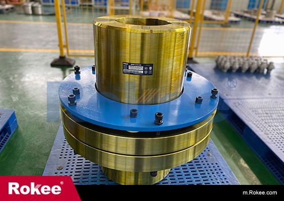
The design of the Bush Pin Coupling is simple and clever in design and has wide applicability. It uses the pin with elastic sleeve to connect two semi-couplings with pin holes to realize torque transmission and larger angular compensation. At the same time, it has good shock absorption and buffering performance, which can be used in high-speed occasions without lubrication and requiring easy pin sleeve replacement.
-
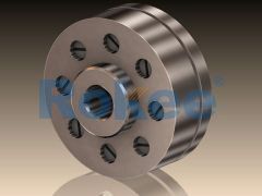
LT/TL Elastic Sleeve Pin Coupling
LT/TL Elastic Sleeve Pin Coupling is the basic form of this series of couplings. -
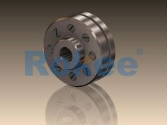
LTZ/TLL Elastic Sleeve Pin Coupling
LTZ/TLL Elastic Sleeve Pin Coupling is designed with a brake wheel, suitable for situations where braking is required.
In the realm of mechanical power transmission, couplings serve as critical components that connect two rotating shafts, enabling the transfer of torque while accommodating misalignments, absorbing shocks, and reducing vibration. Among the diverse range of couplings available, the bush pin coupling stands out for its simplicity, cost-effectiveness, and reliability in various industrial applications.
1. Overview and Definition of Bush Pin Coupling
A bush pin coupling is a type of flexible coupling that utilizes a set of bushings (also known as sleeves) and pins to transmit torque between two shafts. It consists of two flanges, each attached to the ends of the shafts that need to be connected. One of the flanges is equipped with cylindrical pins, while the other flange has corresponding holes fitted with bushings. The pins engage with the bushings, creating a flexible connection that allows for limited angular, parallel, and axial misalignments between the shafts. Unlike rigid couplings, which require precise alignment and cannot absorb shocks, bush pin couplings offer a degree of flexibility that makes them suitable for applications where perfect alignment is difficult to achieve or where shock loads are present.
The primary function of a bush pin coupling is to transmit rotational power from a driving shaft (e.g., from an electric motor or an internal combustion engine) to a driven shaft (e.g., of a pump, compressor, or conveyor). Additionally, it acts as a protective element by absorbing shock loads and vibrations, thereby reducing wear and tear on other components of the mechanical system. The flexibility provided by the bushings also helps to compensate for minor misalignments that may occur due to thermal expansion, shaft deflection, or installation errors.
2. Design and Components of Bush Pin Coupling
The design of a bush pin coupling is relatively straightforward, comprising several key components that work together to ensure efficient torque transmission and flexibility. Each component is designed to fulfill a specific role, and their dimensions and materials are selected based on the application requirements such as torque capacity, operating speed, and environmental conditions.
2.1 Key Components
1. Flanges: The flanges are the main structural components of the coupling, responsible for connecting the coupling to the shafts. They are typically circular in shape and are manufactured from materials such as cast iron, steel, or aluminum. Each flange is drilled with holes to accommodate either the pins or the bushings. The flange attached to the driving shaft (driver flange) is usually the one with the pins, while the flange attached to the driven shaft (driven flange) has the bushing holes. The flanges are secured to the shafts using keys and set screws or by shrink-fitting, ensuring a tight and secure connection that can withstand the transmitted torque.
2. Pins: The pins are cylindrical rods that project from the driver flange. They are evenly spaced around the circumference of the flange to ensure uniform torque distribution. The number and size of the pins depend on the torque capacity required of the coupling. Larger torques require more pins or larger-diameter pins. The pins are typically made from high-strength steel to resist shear forces and wear, as they are in constant contact with the bushings during operation.
3. Bushings: The bushings are cylindrical sleeves that fit into the holes of the driven flange. They are the flexible elements of the coupling, allowing for misalignment and absorbing shocks. The inner diameter of the bushings is slightly larger than the diameter of the pins, creating a clearance that enables relative movement between the pins and bushings. Bushings are commonly made from non-metallic materials such as rubber, nylon, polyurethane, or bakelite. These materials offer good flexibility, wear resistance, and damping properties, which are essential for reducing vibration and noise. In some high-temperature or high-load applications, metallic bushings (e.g., bronze or brass) may be used, although they offer less flexibility compared to non-metallic alternatives.
4. Locking Elements: To prevent the pins from dislodging during operation, locking elements such as split pins, cotter pins, or retaining rings are used. These elements secure the pins in place, ensuring that the connection between the flanges remains intact even under high rotational speeds and torque loads.
2.2 Design Considerations
When designing a bush pin coupling, several factors must be taken into account to ensure its optimal performance and longevity. These include:
- Torque Capacity: The coupling must be designed to handle the maximum torque that will be transmitted between the shafts. This requires calculating the torque based on the power of the driving machine and the operating speed. The number, size, and material of the pins and bushings are selected to meet the torque requirements without failure.
- Misalignment Compensation: The coupling must be able to accommodate the expected misalignments between the shafts. Angular misalignment (tilt between the shafts), parallel misalignment (offset between the shaft axes), and axial misalignment (end-to-end movement of the shafts) are the three main types of misalignments. The design of the bushings and the clearance between the pins and bushings determine the coupling's ability to compensate for these misalignments.
- Operating Speed: The rotational speed of the shafts affects the centrifugal forces acting on the coupling components. At high speeds, the pins and bushings are subjected to increased centrifugal loads, which can lead to premature wear or failure if not considered in the design. The material selection and balancing of the flanges are crucial for high-speed applications.
- Environmental Conditions: The operating environment, including temperature, humidity, exposure to chemicals, and dust, can impact the performance and lifespan of the coupling components. For example, high temperatures can degrade non-metallic bushings, while corrosive environments can damage metal flanges and pins. Therefore, the materials used for the components must be selected to withstand the specific environmental conditions of the application.
3. Working Principle of Bush Pin Coupling
The working principle of a bush pin coupling is based on the transfer of torque through the engagement of pins and bushings, with the bushings providing the necessary flexibility to accommodate misalignments. When the driving shaft rotates, it imparts rotational motion to the driver flange, which in turn causes the pins to rotate. The pins engage with the bushings in the driven flange, transferring the torque to the driven flange and thus to the driven shaft. The clearance between the pins and bushings allows the pins to move slightly within the bushings, enabling the coupling to compensate for misalignments between the two shafts.
During operation, the bushings undergo shear deformation as they transmit torque from the pins to the driven flange. This shear deformation is what allows the coupling to absorb shock loads and vibrations. When a shock load is applied to the system, the bushings act as a buffer, absorbing the impact and reducing the stress transmitted to the shafts and other components. Additionally, the flexibility of the bushings helps to reduce noise generated by the rotating shafts, making the coupling suitable for applications where noise reduction is a priority.
It is important to note that the bush pin coupling is a flexible coupling but has a limited range of misalignment compensation. Exceeding the maximum allowable misalignment can lead to increased wear on the bushings and pins, reduced torque transmission efficiency, and premature failure of the coupling. Therefore, proper alignment of the shafts during installation is still essential, even with the use of a flexible coupling.
4. Material Selection for Bush Pin Coupling Components
The selection of materials for the components of a bush pin coupling is critical to its performance, reliability, and lifespan. The materials must be chosen based on the application requirements, including torque capacity, operating speed, temperature, environmental conditions, and cost. Below is a detailed overview of the commonly used materials for each component:
4.1 Flanges
Flanges are typically made from metallic materials due to their need to withstand high torque and provide structural rigidity. The most commonly used materials for flanges include:
- Cast Iron: Cast iron is a popular choice for flanges due to its high strength, durability, and cost-effectiveness. It has good casting properties, allowing for complex shapes to be manufactured easily. Cast iron flanges are suitable for medium to low torque applications and are commonly used in industrial machinery such as pumps, compressors, and conveyors.
- Steel: Steel flanges are used in high-torque and high-speed applications. They offer higher strength and toughness compared to cast iron, making them suitable for heavy-duty applications such as in steel mills, mining equipment, and large industrial motors. Carbon steel and alloy steel are the most commonly used types of steel for flanges, with alloy steel offering better corrosion resistance and high-temperature performance.
- Aluminum: Aluminum flanges are used in lightweight applications where weight reduction is a priority, such as in automotive and aerospace applications. They have good thermal conductivity and corrosion resistance but are not suitable for high-torque applications due to their lower strength compared to steel and cast iron.
4.2 Pins
Pins are subjected to shear forces and wear during operation, so they must be made from high-strength, wear-resistant materials. The most commonly used materials for pins include:
- High-Strength Steel: Carbon steel and alloy steel are the primary materials used for pins. They offer high shear strength and wear resistance, making them suitable for most industrial applications. Heat treatment is often applied to the pins to further enhance their strength and hardness.
- Stainless Steel: Stainless steel pins are used in corrosive environments where resistance to rust and corrosion is essential. They are commonly used in food processing, pharmaceutical, and marine applications. However, stainless steel has lower shear strength compared to carbon steel, so it may not be suitable for high-torque applications.
4.3 Bushings
Bushings are the flexible elements of the coupling, so their material selection is crucial for providing the necessary flexibility, wear resistance, and damping properties. The most commonly used materials for bushings include:
- Rubber: Rubber bushings are widely used due to their excellent flexibility, shock absorption, and noise reduction properties. They are suitable for low to medium temperature applications and are commonly used in automotive and light industrial applications. However, rubber bushings can degrade over time when exposed to high temperatures, oils, and chemicals.
- Nylon: Nylon bushings offer good wear resistance, low friction, and high tensile strength. They are suitable for medium-temperature applications and are resistant to many chemicals and oils. Nylon bushings are commonly used in industrial machinery, electrical equipment, and automotive applications.
- Polyurethane: Polyurethane bushings combine the flexibility of rubber with the strength of plastic. They offer excellent wear resistance, shock absorption, and resistance to oils and chemicals. They are suitable for high-load and high-temperature applications, making them ideal for heavy-duty industrial machinery.
- Bakelite: Bakelite is a thermosetting plastic that offers good electrical insulation, heat resistance, and wear resistance. It is commonly used in electrical applications where insulation is a priority, such as in electric motors and generators.
- Metallic Bushings: Bronze, brass, and steel bushings are used in high-temperature and high-load applications where non-metallic bushings would degrade. They offer high strength and wear resistance but have lower flexibility compared to non-metallic alternatives. Metallic bushings are often lubricated to reduce friction and wear.
5. Applications of Bush Pin Coupling
Bush pin couplings are widely used in various industrial and commercial applications due to their simplicity, cost-effectiveness, and ability to accommodate misalignments. Their versatility makes them suitable for both light-duty and medium-duty applications, as well as some heavy-duty applications depending on the material selection and design. Below are the typical applications of bush pin couplings:
5.1 Industrial Machinery
One of the most common applications of bush pin couplings is in industrial machinery such as pumps, compressors, fans, blowers, and conveyors. In these applications, the coupling connects the motor (driving shaft) to the machinery (driven shaft), enabling the transfer of torque. The flexibility of the bush pin coupling helps to compensate for misalignments caused by the installation of the machinery and absorbs shocks generated during operation, reducing wear and tear on the motor and the machinery.
For example, in centrifugal pumps, the bush pin coupling connects the electric motor to the pump shaft. The coupling accommodates minor misalignments between the motor and pump shafts, which may occur due to thermal expansion or vibration during operation. This ensures smooth operation of the pump and extends its lifespan.
5.2 Automotive Industry
Bush pin couplings are used in various automotive applications, including in the transmission system, drive shafts, and auxiliary components such as water pumps and alternators. In the transmission system, the coupling helps to transmit torque from the engine to the transmission, absorbing shocks and vibrations that occur during gear shifting. In auxiliary components, the coupling connects the engine to the component, ensuring efficient power transmission while accommodating misalignments.
For instance, in a car's water pump, the bush pin coupling connects the engine's crankshaft to the water pump shaft. The coupling allows for minor misalignments between the two shafts and absorbs vibrations, ensuring the water pump operates smoothly and efficiently.
5.3 Electrical Equipment
Bush pin couplings are used in electrical equipment such as electric motors, generators, and alternators. In electric motors, the coupling connects the motor shaft to the load (e.g., a pump or a fan), enabling the transfer of rotational power. The flexibility of the coupling helps to reduce vibration and noise, which is important for the smooth operation of electrical equipment. In generators and alternators, the coupling connects the prime mover (e.g., a diesel engine) to the generator shaft, ensuring efficient power generation.
5.4 Agricultural Machinery
Agricultural machinery such as tractors, harvesters, and irrigation pumps also use bush pin couplings. In tractors, the coupling connects the engine to the transmission and other auxiliary components, enabling the transfer of torque to power the tractor's wheels and implements. The coupling's ability to accommodate misalignments and absorb shocks is particularly important in agricultural applications, where the machinery operates in rough and uneven terrain.
5.5 Mining and Construction Equipment
In mining and construction equipment such as excavators, loaders, and crushers, bush pin couplings are used to connect the engine to various components such as hydraulic pumps and conveyors. These applications require couplings that can withstand high torque, shock loads, and harsh environmental conditions. Bush pin couplings made from high-strength materials such as steel and polyurethane are suitable for these heavy-duty applications, providing reliable torque transmission and durability.
6. Installation and Alignment Procedures
Proper installation and alignment of a bush pin coupling are essential for its optimal performance and longevity. Incorrect installation or misalignment can lead to increased wear on the components, reduced torque transmission efficiency, and premature failure of the coupling. Below is a step-by-step guide to the installation and alignment procedures:
6.1 Preparation
Before installing the coupling, it is important to prepare the shafts and the coupling components. This includes:
- Cleaning the shaft ends to remove any dirt, rust, or debris. This ensures a tight and secure fit between the flanges and the shafts.
- Checking the shaft diameters to ensure they match the inner diameter of the flanges. If necessary, machine the shafts to the correct size.
- Inspecting the coupling components (flanges, pins, bushings, and locking elements) for any damage or defects. Replace any damaged components before installation.
6.2 Mounting the Flanges
The next step is to mount the flanges onto the shafts. This involves:
- Sliding the driver flange onto the driving shaft and the driven flange onto the driven shaft. Ensure that the flanges are positioned correctly, with the pins and bushing holes aligned.
- Securing the flanges to the shafts using keys and set screws. The key is inserted into the keyway of the shaft and the flange, ensuring that the flange rotates with the shaft. The set screws are then tightened to hold the flange in place. Alternatively, shrink-fitting may be used for a more secure connection in high-torque applications.
6.3 Aligning the Shafts
Proper alignment of the shafts is crucial for the performance of the bush pin coupling. The following steps are involved in aligning the shafts:
- Checking angular misalignment: Angular misalignment occurs when the shafts are not parallel but intersect at a point. To check angular misalignment, place a straightedge across the flanges. If there is a gap between the straightedge and the flange at any point, it indicates angular misalignment. Adjust the position of the motor or the driven machinery to eliminate the gap.
- Checking parallel misalignment: Parallel misalignment occurs when the shafts are parallel but offset from each other. To check parallel misalignment, measure the distance between the flanges at several points around the circumference. If the distance varies, it indicates parallel misalignment. Adjust the position of the motor or the driven machinery to ensure that the distance is uniform around the circumference.
- Using alignment tools: For more precise alignment, tools such as dial indicators or laser alignment tools can be used. These tools measure the misalignment accurately, allowing for precise adjustment of the shafts. The maximum allowable misalignment for bush pin couplings typically ranges from 0.5 to 1.5 mm for parallel misalignment and 0.5 to 1 degree for angular misalignment, depending on the coupling size and design.
6.4 Assembling the Coupling
Once the shafts are aligned, the coupling can be assembled. This involves:
- Inserting the bushings into the holes of the driven flange. Ensure that the bushings fit snugly in the holes.
- Positioning the driver flange (with the pins) against the driven flange (with the bushings), ensuring that the pins engage with the bushings.
- Securing the pins in place using the locking elements (split pins, cotter pins, or retaining rings). Ensure that the locking elements are properly installed to prevent the pins from dislodging during operation.
6.5 Final Checks
After assembling the coupling, perform the following final checks:
- Rotate the shafts manually to ensure that the coupling rotates smoothly without any binding or excessive play.
- Check the alignment again to ensure that no misalignment was introduced during the assembly process.
- Tighten any loose set screws or bolts to ensure a secure connection.
7. Maintenance Practices for Bush Pin Coupling
Regular maintenance of bush pin couplings is essential to ensure their reliable performance and extend their lifespan. Maintenance practices typically involve inspection, lubrication, and replacement of worn components. Below are the key maintenance practices for bush pin couplings:
7.1 Regular Inspection
Regular inspection of the coupling components helps to identify any signs of wear, damage, or misalignment early, preventing costly repairs and downtime. The inspection should be performed at regular intervals, depending on the application and operating conditions. The key areas to inspect include:
- Bushings: Check for signs of wear, cracking, or deformation. Worn bushings can cause increased play between the pins and bushings, leading to excessive vibration and noise. If the bushings are worn beyond the acceptable limit, they should be replaced.
- Pins: Inspect the pins for signs of wear, bending, or shear damage. Worn pins can reduce the torque transmission capacity of the coupling and may lead to failure. Replace any damaged or worn pins.
- Flanges: Check the flanges for cracks, corrosion, or loose set screws. Cracks in the flanges can compromise the structural integrity of the coupling, leading to failure. Tighten any loose set screws and replace any cracked or corroded flanges.
- Locking Elements: Inspect the split pins, cotter pins, or retaining rings to ensure they are intact and properly installed. Missing or damaged locking elements can cause the pins to dislodge during operation, leading to coupling failure.
- Alignment: Check the alignment of the shafts regularly, as misalignment can develop over time due to thermal expansion, shaft deflection, or wear on the mounting components. Re-align the shafts if necessary.
7.2 Lubrication
Lubrication is essential for reducing friction and wear between the pins and bushings. The type of lubricant used depends on the material of the bushings and the operating conditions. For metallic bushings, grease or oil lubrication is typically used. For non-metallic bushings, lubrication may not be required, as they have inherent low-friction properties. However, in some cases, a light coat of grease may be applied to reduce wear.
The lubrication interval depends on the operating speed, load, and environmental conditions. In general, lubrication should be performed every 6 to 12 months, or more frequently in high-speed or high-load applications. When lubricating, ensure that the lubricant reaches all the moving parts of the coupling. Excess lubricant should be removed to prevent the accumulation of dirt and debris.
7.3 Replacement of Worn Components
Worn or damaged components should be replaced promptly to prevent further damage to the coupling and other parts of the mechanical system. When replacing components, it is important to use components that are compatible with the coupling's design and specifications. This includes using the correct size and material of pins, bushings, and flanges.
When replacing bushings, ensure that they fit snugly in the holes of the driven flange. Loose bushings can cause excessive play and vibration. When replacing pins, ensure that they are properly secured with locking elements to prevent dislodgment. After replacing components, re-check the alignment of the shafts and perform a test run to ensure the coupling operates smoothly.
7.4 Storage and Handling
Proper storage and handling of bush pin couplings are also important for maintaining their performance. Couplings should be stored in a clean, dry environment to prevent rust and corrosion. They should be kept away from direct sunlight, moisture, and chemicals that can degrade the components. When handling the coupling, avoid dropping or striking it, as this can cause damage to the flanges, pins, or bushings.
8. Advantages and Disadvantages of Bush Pin Coupling
Like any other coupling type, bush pin couplings have their own set of advantages and disadvantages. Understanding these can help engineers and maintenance professionals determine whether a bush pin coupling is suitable for a specific application.
8.1 Advantages
- Simplicity and Cost-Effectiveness: Bush pin couplings have a simple design, making them easy to manufacture and install. They are also more cost-effective compared to other types of flexible couplings such as gear couplings or disc couplings, making them an ideal choice for budget-conscious applications.
- Flexibility: The bushings provide a degree of flexibility that allows the coupling to accommodate minor angular, parallel, and axial misalignments. This reduces the need for precise alignment during installation and compensates for misalignments that develop during operation.
- Shock and Vibration Absorption: The flexible bushings absorb shock loads and vibrations, reducing wear and tear on the shafts, bearings, and other components of the mechanical system. This also helps to reduce noise generated by the rotating shafts.
- Easy Maintenance: Bush pin couplings are easy to maintain, with simple inspection and replacement of worn components. The bushings and pins can be replaced without removing the entire coupling from the shafts, reducing downtime.
- Versatility: Bush pin couplings are available in a wide range of sizes and materials, making them suitable for various applications, from light-duty to heavy-duty.
8.2 Disadvantages
- Limited Misalignment Capacity: While bush pin couplings can accommodate minor misalignments, their misalignment capacity is limited compared to other flexible couplings such as universal joints or elastomeric couplings. Exceeding the maximum allowable misalignment can lead to premature wear and failure.
- Lower Torque Capacity: Bush pin couplings have a lower torque capacity compared to rigid couplings or gear couplings. This makes them unsuitable for very high-torque applications.
- Bushing Wear: The bushings are subject to wear during operation, especially in high-speed or high-load applications. This requires regular inspection and replacement of the bushings to ensure the coupling's performance.
- Not Suitable for High-Temperature Applications: Non-metallic bushings can degrade at high temperatures, limiting the use of bush pin couplings in high-temperature environments. Metallic bushings can be used, but they offer less flexibility.
9. Future Trends in Bush Pin Coupling Design
The design and development of bush pin couplings are continuously evolving to meet the changing needs of industrial applications. Some of the future trends in bush pin coupling design include:
- Use of Advanced Materials: The development of new materials such as high-performance polymers, composite materials, and advanced alloys is expected to improve the performance and lifespan of bush pin couplings. These materials offer better wear resistance, high-temperature performance, and corrosion resistance compared to traditional materials.
- Improved Design for Higher Misalignment Capacity: Engineers are working on improving the design of bush pin couplings to increase their misalignment capacity, making them suitable for applications where larger misalignments are expected. This may involve modifying the shape and size of the bushings and pins to allow for greater relative movement.
- Integration of Smart Technologies: The integration of smart technologies such as sensors and monitoring systems into bush pin couplings is a growing trend. These sensors can monitor the coupling's performance, including temperature, vibration, and wear, providing real-time data to maintenance professionals. This allows for predictive maintenance, reducing downtime and improving the reliability of the mechanical system.
- Lightweight Design: With the increasing focus on energy efficiency and weight reduction, there is a trend towards designing lightweight bush pin couplings. This involves using lightweight materials such as aluminum and composite materials, as well as optimizing the design of the flanges and other components to reduce weight without compromising strength.
10. Conclusion
Bush pin couplings are essential components in mechanical power transmission systems, offering a simple, cost-effective, and reliable solution for connecting rotating shafts. Their design, which utilizes bushings and pins, provides the necessary flexibility to accommodate misalignments, absorb shocks, and reduce vibration. The selection of materials for the components is crucial for ensuring the coupling's performance and longevity, with different materials suitable for different applications based on torque capacity, operating speed, and environmental conditions.
Proper installation, alignment, and maintenance are essential for the optimal performance of bush pin couplings. Regular inspection, lubrication, and replacement of worn components can extend the coupling's lifespan and prevent costly downtime. While bush pin couplings have some limitations, such as limited misalignment capacity and lower torque capacity, their advantages make them suitable for a wide range of applications, from light-duty industrial machinery to heavy-duty mining equipment.
As technology advances, the design of bush pin couplings is expected to evolve, with the use of advanced materials, improved misalignment capacity, and integration of smart technologies. These advancements will further enhance the performance and reliability of bush pin couplings, making them an even more valuable component in mechanical power transmission systems.
« Bush Pin Coupling » Post Date: 2023/8/19
URL: https://www.rokeecoupling.com/en/tags/bush-pin-coupling.html
- 2024-02-28Bush Pin Coupling Price
- 2024-02-28Bush Pin Coupling Picture
- 2024-02-28Bush Pin Coupling Models
- 2024-02-28Bush Pin Coupling Manufacturing
- 2024-02-28Bush Pin Coupling Drawing
- 2024-02-28Bush Pin Coupling Design
- 2024-02-28Bush Pin Coupling Calculation
- 2024-02-28Schematic Diagram of Bush Pin Couplings
- 2024-02-28Purpose of Bush Pin Couplings
- 2024-02-28Procurement of Bush Pin Coupling
- 2024-02-28Parts of Bush Pin Coupling
- 2024-02-28Misalignment Tolerance of Bush Pin Coupling
- 2024-02-28Material of Bush Pin Coupling
- 2024-02-28Maintenance of Bush Pin Coupling
- 2024-02-28Lubrication of Bush Pin Coupling
- 2024-02-28Installation of Bush Pin Coupling
- 2024-02-28Grease of Bush Pin Coupling
- 2024-02-28Gap Chart of Bush Pin Coupling
- 2024-02-28Function of Bush Pin Coupling
- 2024-02-28Exploded View of Bush Pin Couplings
- 2024-02-04Efficiency of Bush Pin Coupling
- 2024-02-04Disadvantages of Bush Pin Coupling
- 2024-02-04Custom Bush Pin Couplings
- 2024-02-04Components of Bush Pin Coupling
- 2024-02-04Coaxiality of Bush Pin Coupling
- 2024-02-04Classification of Bush Pin Couplings
- 2024-02-04Bush Pin Coupling Assembly Drawing
- 2024-02-04Bush Pin Coupling Advantages
- 2024-02-04Application of Bush Pin Coupling
- 2024-02-04Angle of Bush Pin Coupling
- 2024-02-04Alignment of Bush Pin Coupling
- 2024-02-043D Model of Bush Pin Coupling
- 2024-02-04Working Principle of Bush Pin Coupling
- 2024-02-04Uses of Bush Pin Coupling
- 2024-02-04Types of Bush Pin Coupling
- 2024-02-04Torque of Bush Pin Coupling
- 2024-02-04Supply of Bush Pin Couplings
- 2024-02-04Structural Diagram of Bush Pin Couplings
- 2024-02-04Stiffness of Bush Pin Coupling
- 2024-02-04Specifications of Bush Pin Coupling
- 2024-02-04Size Chart of Bush Pin Couplings
- 2024-02-04High Quality Bush Pin Couplings
- 2024-02-04High Performance Bush Pin Couplings
- 2024-02-04Bush Pin Couplings Wholesale
- 2024-02-04Bush Pin Couplings Supplier
- 2024-02-04Bush Pin Couplings Manufacturer
- 2024-02-04Bush Pin Couplings For Sale
- 2024-02-04Bush Pin Couplings Factory
- 2024-02-04Bush Pin Couplings Company
- 2024-02-04Bush Pin Coupling Standard Sizes
- 2024-01-22Tagging of Bush Pin Coupling
- 2024-01-22Size Calculation of Bush Pin Coupling
- 2024-01-22Engineering Drawing of Bush Pin Couplings
- 2024-01-22Catalogue of Bush Pin Couplings
- 2024-01-22Bush Pin Coupling Sales
- 2024-01-22Bush Pin Coupling Brands
- 2024-01-17Machine Drawing of Bush Pin Couplings