Crown Pin Couplings
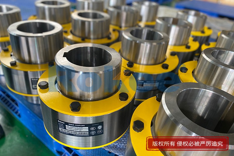
Rokee® is Crown Pin Couplings Supplier from China, Support Customization and Export, due to excellent quality, complete technical services and superior cost performance, Rokee® Crown Pin Couplings have been serving more than 60 countries and regions in the world, effectively operating in many corners of the world.
The Crown Pin Coupling is designed with non-metallic flexible pin, two toothed semi-couplings and a toothed sleeve ring with an outer ring. Crown Pin Coupling uses non-metallic flexible deformation to transfer torque and cushion shock and compensate angular displacement.
-
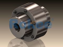
LZ/ZL Pin Gear Coupling
LZ Pin Gear Coupling is the basic form of this series of couplings. -
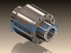
LZD/ZLD Pin Gear Coupling
One end of the LZD Pin Gear Coupling is designed with a conical shaft hole, and the clearance between the semi-couplings is increased to facilitate the fixing space at the shaft end. -
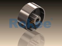
LZZ/ZLL Pin Gear Coupling
LZZ Pin Gear Coupling is designed with a brake wheel, suitable for situations where braking is required.
In the realm of mechanical power transmission, couplings serve as critical components that connect two rotating shafts, enabling the transfer of torque while accommodating misalignments and absorbing shock loads. Among the diverse range of couplings available, the crown pin coupling stands out for its unique design characteristics and reliable performance in various industrial settings.
1. Overview and Structural Composition of Crown Pin Couplings
A crown pin coupling is a type of rigid-flexible coupling that combines the advantages of both rigid and flexible couplings, making it suitable for applications where moderate misalignments and shock absorption are required. Unlike fully rigid couplings that demand precise alignment between shafts, crown pin couplings can accommodate small to moderate amounts of angular, parallel, and axial misalignments, thereby reducing the stress on shafts, bearings, and other related components. The core structure of a crown pin coupling consists of several key components, each playing a vital role in ensuring its overall functionality.
The primary components of a crown pin coupling include two hubs, a crown wheel (also known as a crown gear), pin shafts, and a coupling sleeve. The hubs are designed to be mounted on the ends of the two shafts that need to be connected. They are typically secured to the shafts using keyways, set screws, or hydraulic mounting methods, ensuring a tight and secure fit that prevents slippage during torque transmission. The crown wheel is attached to one of the hubs and features a series of evenly spaced slots or grooves along its circumference. These slots are designed to engage with the pin shafts, which are mounted on the coupling sleeve.
The coupling sleeve serves as the connecting element between the two hubs, housing the pin shafts that interact with the crown wheel. The pin shafts are usually cylindrical in shape and are mounted in the sleeve at equal intervals, corresponding to the slots on the crown wheel. In some designs, the pin shafts may be fitted with bushings or bearings to reduce friction between the pins and the crown wheel slots, enhancing the coupling's durability and reducing wear. The interaction between the crown wheel and the pin shafts allows for relative movement between the two hubs, enabling the coupling to accommodate misalignments. Additionally, the design may include a cover or housing to protect the internal components from dust, debris, and other environmental contaminants, which can degrade the performance of the coupling over time.
One of the distinguishing features of crown pin couplings is their compact design, which makes them suitable for applications where space is limited. Compared to other types of flexible couplings such as jaw couplings or tire couplings, crown pin couplings have a smaller footprint while maintaining a high torque transmission capacity. This compactness, combined with their ability to handle misalignments, makes them a preferred choice in many industrial applications.
2. Working Principle of Crown Pin Couplings
The working principle of a crown pin coupling revolves around the meshing of the crown wheel and the pin shafts, which enables the transfer of torque from one shaft to another while accommodating relative movement between the shafts. When the driving shaft rotates, it transmits torque to the hub attached to it, which in turn rotates the crown wheel. As the crown wheel rotates, the slots on its circumference engage with the pin shafts mounted on the coupling sleeve. This engagement causes the coupling sleeve to rotate, transferring the torque to the second hub and ultimately to the driven shaft.
The key to the coupling's ability to accommodate misalignments lies in the design of the crown wheel and pin shaft interaction. The slots on the crown wheel are typically curved or angled, allowing the pin shafts to move within the slots as the shafts misalign. For angular misalignment (where the two shafts are not collinear but intersect at a point), the pin shafts can pivot within the slots, enabling the crown wheel to rotate relative to the coupling sleeve without causing excessive stress. For parallel misalignment (where the two shafts are parallel but offset), the linear movement of the pin shafts within the slots accommodates the offset, ensuring smooth torque transmission.
Axial misalignment (where the two shafts move towards or away from each other) is also accommodated by the crown pin coupling. The length of the pin shafts and the depth of the crown wheel slots allow for a certain amount of axial movement, preventing the coupling from binding or causing damage to the shafts. Additionally, the coupling can absorb shock loads and vibrations generated during operation. When a shock load is applied to the driving shaft, the interaction between the crown wheel and the pin shafts acts as a buffer, dissipating the shock and reducing its impact on the driven shaft and other components of the mechanical system.
It is important to note that the crown pin coupling is not designed to accommodate excessive misalignments. Exceeding the recommended misalignment limits can lead to increased wear on the pin shafts and crown wheel slots, reduced torque transmission efficiency, and premature failure of the coupling. Therefore, proper alignment during installation is crucial to ensure optimal performance and longevity of the coupling.
3. Material Selection for Crown Pin Couplings
The selection of materials for crown pin coupling components is a critical factor that directly impacts the coupling's performance, durability, and suitability for specific applications. The materials must be chosen based on various factors, including the torque capacity required, the operating environment (temperature, humidity, presence of corrosive substances), the speed of rotation, and the load conditions (static, dynamic, shock loads). The following are the commonly used materials for different components of crown pin couplings:
For the hubs and coupling sleeve, carbon steel and alloy steel are the most widely used materials. Carbon steel, such as A36 or 1045 steel, offers good strength and durability at a relatively low cost, making it suitable for general-purpose applications with moderate torque requirements. Alloy steel, such as 4140 or 4340 steel, has higher strength and toughness compared to carbon steel, making it ideal for high-torque applications or environments where the coupling is subjected to heavy shock loads. In some cases, cast iron may be used for hubs and sleeves in low-torque, low-speed applications due to its good machinability and cost-effectiveness.
The crown wheel and pin shafts are typically made from high-strength materials to withstand the wear and stress generated during torque transmission. Alloy steel is commonly used for these components, often heat-treated to enhance their hardness and wear resistance. Heat treatment processes such as quenching and tempering are applied to improve the mechanical properties of the steel, making it more resistant to fatigue and wear. For applications where corrosion resistance is a concern, stainless steel may be used for the crown wheel and pin shafts. Stainless steel, such as 304 or 316, offers excellent corrosion resistance in harsh environments, including those with high humidity, chemical exposure, or marine conditions.
Bushings or bearings used in the pin shafts are often made from bronze, brass, or composite materials. Bronze and brass have good lubricity and wear resistance, reducing friction between the pin shafts and the crown wheel slots. Composite materials, such as polytetrafluoroethylene (PTFE) or nylon, are also used for bushings due to their self-lubricating properties, which eliminate the need for frequent lubrication and reduce maintenance requirements. These composite materials are particularly suitable for applications where lubrication is difficult or where contamination from lubricants must be avoided.
In high-temperature applications, such as those in the steel industry or power generation plants, materials that can withstand elevated temperatures are required. In such cases, heat-resistant alloys, such as Inconel or Hastelloy, may be used for critical components. These alloys retain their strength and mechanical properties at high temperatures, ensuring the coupling's performance is not compromised.
4. Applications of Crown Pin Couplings Across Industries
Crown pin couplings are widely used in various industries due to their versatile design, reliable torque transmission, and ability to accommodate moderate misalignments. Their compact size and shock absorption capabilities make them suitable for a wide range of applications, from light-duty to heavy-duty operations. The following are some of the key industries where crown pin couplings are commonly employed:
4.1 Manufacturing and Processing Industry: In the manufacturing sector, crown pin couplings are used in a variety of machinery, including conveyors, pumps, compressors, and mixers. Conveyors, which are used to transport materials across production facilities, rely on couplings to connect the motor to the conveyor belt drive shaft. Crown pin couplings are ideal for this application as they can accommodate the slight misalignments that may occur due to the long length of the conveyor shafts and the vibrations generated during operation. Pumps and compressors, which are essential for fluid and gas transfer, also benefit from the use of crown pin couplings. These couplings ensure efficient torque transmission from the motor to the pump or compressor shaft, while absorbing the shock loads generated by the reciprocating motion of the pump pistons or compressor rotors.
4.2 Automotive and Transportation Industry: In the automotive industry, crown pin couplings are used in various components of vehicles, such as the transmission system, drivetrain, and auxiliary systems. For example, in some commercial vehicles, crown pin couplings are used to connect the engine to the transmission, enabling the transfer of torque while accommodating the misalignments that may occur due to the movement of the engine and transmission during vehicle operation. They are also used in the drivetrain of off-road vehicles, where they can withstand the harsh operating conditions and shock loads encountered during off-road driving. Additionally, crown pin couplings are used in auxiliary systems such as power steering pumps and air conditioning compressors, ensuring reliable power transmission to these components.
4.3 Power Generation Industry: Power generation plants, including thermal power plants, hydroelectric power plants, and wind farms, rely on crown pin couplings for various applications. In thermal power plants, crown pin couplings are used to connect the turbine to the generator, enabling the transfer of the high torque generated by the turbine to the generator rotor. The coupling's ability to accommodate slight misalignments is crucial in this application, as the turbine and generator shafts must be aligned with high precision to ensure efficient power generation. In hydroelectric power plants, crown pin couplings are used in the turbine-generator set, as well as in the auxiliary systems such as water pumps and cooling fans. In wind farms, crown pin couplings are used in the wind turbine drivetrain, connecting the rotor to the gearbox and the gearbox to the generator. They help to absorb the variable torque and shock loads generated by the wind, ensuring smooth and reliable power transmission.
4.4 Mining and Construction Industry: The mining and construction industries operate in harsh environments where machinery is subjected to heavy loads, shock, and vibrations. Crown pin couplings are widely used in mining equipment such as crushers, conveyors, and excavators. Crushers, which are used to break down large rocks into smaller particles, rely on crown pin couplings to connect the motor to the crusher shaft. The coupling's shock absorption capabilities help to protect the motor and crusher components from the impact of the rocks being crushed. Conveyors used in mining operations to transport ore and other materials also use crown pin couplings, which can accommodate the misalignments caused by the uneven terrain and the long length of the conveyor systems. In construction equipment such as excavators and bulldozers, crown pin couplings are used in the drivetrain and hydraulic systems, ensuring reliable power transmission to the wheels or tracks.
4.5 Agricultural Industry: In the agricultural industry, crown pin couplings are used in various farm machinery, such as tractors, harvesters, and irrigation pumps. Tractors use crown pin couplings to connect the engine to the transmission and to power take-off (PTO) shafts, which are used to drive auxiliary equipment such as plows, harrows, and balers. The coupling's ability to accommodate misalignments and absorb shock loads is essential in this application, as the PTO shaft may be subjected to varying loads and angles during operation. Harvesters, such as combine harvesters, also use crown pin couplings in their drivetrain and processing components, ensuring efficient power transmission to the cutting, threshing, and cleaning mechanisms. Irrigation pumps, which are used to supply water to farm fields, rely on crown pin couplings to connect the motor to the pump shaft, enabling reliable water transfer even in outdoor environments with varying temperature and humidity conditions.
5. Installation and Maintenance of Crown Pin Couplings
Proper installation and regular maintenance are essential to ensure the optimal performance and longevity of crown pin couplings. Improper installation can lead to excessive misalignments, increased wear, and premature failure of the coupling, while inadequate maintenance can result in the accumulation of dirt and debris, lubrication failure, and component damage. The following are the key steps and best practices for the installation and maintenance of crown pin couplings:
5.1 Installation Process: The installation of a crown pin coupling involves several critical steps, starting with the preparation of the shafts. Before mounting the hubs, the shafts should be cleaned thoroughly to remove any dirt, rust, or oil, which can prevent a secure fit. The keyways on the shafts and hubs should also be inspected to ensure they are free from burrs and damage. If necessary, the keyways should be deburred using a file or sandpaper to ensure a proper fit of the key.
Next, the hubs are mounted on the respective shafts. The hubs should be pressed or heated onto the shafts to ensure a tight interference fit. When using heat, the hub should be heated uniformly to avoid distortion, and then slipped onto the shaft while it is still hot. Once the hub cools down, it will contract, creating a secure fit on the shaft. Set screws or locking nuts may be used to further secure the hubs to the shafts, ensuring they do not slip during operation.
After mounting the hubs, the crown wheel and coupling sleeve are installed. The crown wheel is attached to one of the hubs using bolts or screws, ensuring it is aligned correctly. The coupling sleeve, with the pin shafts installed, is then positioned over the crown wheel, engaging the pin shafts with the slots on the crown wheel. The two hubs should be aligned as closely as possible to minimize misalignment. A dial indicator or laser alignment tool can be used to measure the angular and parallel misalignments, which should be within the recommended limits specified by the coupling manufacturer.
Finally, the cover or housing is installed to protect the internal components of the coupling. The cover should be secured tightly to prevent the entry of dust, debris, and moisture. If the coupling requires lubrication, the appropriate lubricant should be applied to the pin shafts and crown wheel slots before installing the cover. The type and amount of lubricant should be in accordance with the manufacturer's recommendations.
5.2 Maintenance Practices: Regular maintenance of crown pin couplings involves periodic inspection, lubrication, and replacement of worn components. The frequency of maintenance depends on the operating conditions, such as the speed of rotation, torque load, and environmental factors. In general, couplings should be inspected at least once every six months, or more frequently in harsh operating environments.
During inspection, the coupling should be checked for signs of wear, such as worn pin shafts, damaged crown wheel slots, or loose hubs. The cover should be removed to inspect the internal components, and any dirt, debris, or old lubricant should be cleaned out. The alignment of the shafts should also be rechecked, as misalignments can develop over time due to component wear or mechanical stress. If misalignments exceed the recommended limits, the coupling should be realigned immediately.
Lubrication is a critical aspect of crown pin coupling maintenance. Proper lubrication reduces friction between the pin shafts and crown wheel slots, minimizing wear and extending the life of the coupling. The lubricant should be checked regularly to ensure it is clean and at the correct level. If the lubricant is contaminated or degraded, it should be drained and replaced with the recommended type. Some couplings use self-lubricating bushings, which do not require regular lubrication but should be inspected for wear periodically.
Worn components, such as pin shafts, bushings, or crown wheels, should be replaced promptly to prevent further damage to the coupling and other components of the mechanical system. When replacing components, it is important to use parts that are compatible with the coupling model and specifications. Using non-genuine or incompatible parts can lead to poor performance and premature failure.
In addition to regular inspection and lubrication, it is important to monitor the coupling's performance during operation. Unusual noises, vibrations, or a decrease in torque transmission efficiency may indicate a problem with the coupling, such as worn components or misalignment. These issues should be addressed immediately to avoid costly downtime and repairs.
6. Emerging Trends in Crown Pin Coupling Design and Manufacturing
The field of mechanical power transmission is constantly evolving, driven by advancements in technology, increasing demand for energy efficiency, and the need for more reliable and durable components. Crown pin couplings are no exception, and several emerging trends are shaping their design and manufacturing. These trends aim to improve the performance, efficiency, and sustainability of crown pin couplings, making them more suitable for the evolving needs of modern industries.
One of the key trends is the adoption of computer-aided design (CAD) and finite element analysis (FEA) in the design process. CAD software allows engineers to create detailed 3D models of crown pin couplings, enabling them to optimize the design for maximum torque capacity, minimal weight, and improved misalignment accommodation. FEA is used to simulate the performance of the coupling under various operating conditions, such as different torque loads, misalignments, and temperature ranges. This simulation helps to identify potential stress points and areas of wear, allowing engineers to modify the design to enhance durability and reduce the risk of premature failure. By using CAD and FEA, manufacturers can develop crown pin couplings that are more efficient and reliable, while reducing the time and cost of the design process.
Another trend is the use of advanced materials and manufacturing processes. The development of new high-strength, lightweight materials, such as carbon fiber composites and titanium alloys, is enabling the production of crown pin couplings that are lighter, stronger, and more corrosion-resistant than traditional steel couplings. These materials are particularly suitable for applications where weight reduction is critical, such as in the automotive and aerospace industries. Additionally, advanced manufacturing processes such as additive manufacturing (3D printing) are being used to produce complex components of crown pin couplings with high precision. 3D printing allows for the creation of intricate designs that are difficult or impossible to achieve with traditional machining methods, enabling the optimization of the coupling's performance. It also reduces material waste and allows for the production of small batches of customized couplings, meeting the specific needs of individual applications.
The integration of smart technologies into crown pin couplings is another emerging trend. Smart couplings are equipped with sensors that monitor various parameters such as temperature, vibration, torque, and misalignment. These sensors transmit real-time data to a central monitoring system, allowing engineers to track the performance of the coupling and detect potential issues before they lead to failure. Predictive maintenance algorithms can analyze the data to predict when maintenance or component replacement will be required, enabling proactive maintenance and reducing downtime. Smart couplings are particularly useful in critical applications such as power generation and mining, where unplanned downtime can result in significant financial losses.
Finally, there is a growing focus on sustainability in the design and manufacturing of crown pin couplings. Manufacturers are striving to reduce the environmental impact of their products by using recycled materials, optimizing the design to reduce material usage, and implementing energy-efficient manufacturing processes. Additionally, the development of long-lasting, low-maintenance couplings reduces the need for frequent replacement, minimizing waste. These sustainable practices not only benefit the environment but also help manufacturers reduce costs and meet the increasing demand for eco-friendly products from customers and regulatory bodies.
7. Conclusion
Crown pin couplings are essential components in mechanical power transmission systems, offering a unique combination of rigid torque transmission and flexible misalignment accommodation. Their compact design, reliable performance, and ability to absorb shock loads make them suitable for a wide range of applications across various industries, including manufacturing, automotive, power generation, mining, and agriculture. The selection of appropriate materials, proper installation, and regular maintenance are critical to ensuring the optimal performance and longevity of crown pin couplings.
As technology continues to advance, the design and manufacturing of crown pin couplings are evolving, with trends such as CAD/FEA design, advanced materials, additive manufacturing, smart technologies, and sustainability shaping the future of these components. These advancements are enabling the production of crown pin couplings that are more efficient, durable, and environmentally friendly, meeting the evolving needs of modern industries.
In conclusion, a thorough understanding of crown pin couplings, including their structure, working principle, material selection, applications, and maintenance requirements, is essential for engineers and maintenance professionals to select and utilize these components effectively. By staying abreast of emerging trends in coupling design and manufacturing, they can leverage the latest technologies to optimize the performance of mechanical systems, reduce downtime, and improve overall operational efficiency.
« Crown Pin Couplings » Post Date: 2023/8/31
URL: https://www.rokeecoupling.com/en/tags/crown-pin-couplings.html
- 2024-01-29Torque of Crown Pin Coupling
- 2024-01-29Tagging of Crown Pin Coupling
- 2024-01-29Supply of Crown Pin Couplings
- 2024-01-29Structural Diagram of Crown Pin Couplings
- 2024-01-29Stiffness of Crown Pin Coupling
- 2024-01-29Size Chart of Crown Pin Couplings
- 2024-01-29Size Calculation of Crown Pin Coupling
- 2024-01-29Schematic Diagram of Crown Pin Couplings
- 2024-01-29Purpose of Crown Pin Couplings
- 2024-01-29Procurement of Crown Pin Coupling
- 2024-01-29Parts of Crown Pin Coupling
- 2024-01-29Uses of Crown Pin Couplings
- 2024-01-29Working Principle of Crown Pin Coupling
- 2024-01-29Material of Crown Pin Coupling
- 2024-01-29Maintenance of Crown Pin Coupling
- 2024-01-29Machine Drawing of Crown Pin Couplings
- 2024-01-29Lubrication of Crown Pin Coupling
- 2024-01-29Installation of Crown Pin Coupling
- 2024-01-29High Quality Crown Pin Couplings
- 2024-01-29Grease of Crown Pin Coupling
- 2024-01-29Gap Chart of Crown Pin Couplings
- 2024-01-29Function of Crown Pin Couplings
- 2024-01-29Exploded View of Crown Pin Couplings
- 2024-01-29Engineering Drawing of Crown Pin Couplings
- 2024-01-29Efficiency of Crown Pin Coupling
- 2024-01-29Disadvantages of Crown Pin Couplings
- 2024-01-22Types of Crown Pin Coupling
- 2024-01-22Specifications of Crown Pin Coupling
- 2024-01-22Misalignment Tolerance of Crown Pin Coupling
- 2024-01-22High Performance Crown Pin Couplings
- 2024-01-22Custom Crown Pin Couplings
- 2024-01-16Crown Pin Couplings Wholesale
- 2024-01-16Crown Pin Couplings Supplier
- 2024-01-16Crown Pin Couplings Manufacturer
- 2024-01-16Crown Pin Couplings For Sale
- 2024-01-16Crown Pin Couplings Factory
- 2024-01-16Crown Pin Couplings Company
- 2024-01-16Crown Pin Coupling Standard Sizes
- 2024-01-16Crown Pin Coupling Sales
- 2024-01-16Crown Pin Coupling Price
- 2024-01-16Crown Pin Coupling Picture
- 2024-01-16Crown Pin Coupling Models
- 2024-01-16Crown Pin Coupling Manufacturing
- 2024-01-16Crown Pin Coupling Drawing
- 2024-01-16Crown Pin Coupling Design
- 2024-01-16Crown Pin Coupling Calculation
- 2024-01-16Crown Pin Coupling Brands
- 2024-01-16Crown Pin Coupling Assembly Drawing
- 2024-01-16Crown Pin Coupling Advantages
- 2024-01-16Components of Crown Pin Coupling
- 2024-01-16Coaxiality of Crown Pin Coupling
- 2024-01-16Classification of Crown Pin Couplings
- 2024-01-16Catalogue of Crown Pin Couplings
- 2024-01-16Application of Crown Pin Couplings
- 2024-01-16Angle of Crown Pin Coupling
- 2024-01-16Alignment of Crown Pin Coupling
- 2024-01-163D Model of Crown Pin Couplings