
Rokee® is Centrifugal Pump Coupling Supplier from China, Support Customization and Export, due to excellent quality, complete technical services and superior cost performance, Rokee® Centrifugal Pump Coupling have been serving more than 60 countries and regions in the world, effectively operating in many corners of the world.
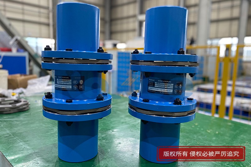
Centrifugal pumps are indispensable assets in numerous industrial, commercial, and municipal applications, responsible for transferring fluids efficiently across various systems. From water treatment plants and oil refineries to HVAC systems and agricultural irrigation, these pumps play a critical role in maintaining operational continuity. While the impeller, volute, and motor are often the focus of attention when discussing centrifugal pump performance, the coupling—a seemingly modest yet vital component—serves as the linchpin between the motor and the pump. It is the coupling that transmits rotational power from the motor to the pump shaft, enabling the conversion of mechanical energy into fluid flow. Despite its unassuming appearance, the proper selection, installation, and maintenance of centrifugal pump couplings are paramount to ensuring system reliability, minimizing downtime, and optimizing energy efficiency.
At its core, a centrifugal pump coupling is a mechanical device designed to connect two rotating shafts—the output shaft of the motor and the input shaft of the pump—while accommodating minor misalignments and transmitting torque seamlessly. Beyond mere power transmission, couplings serve several other critical functions that contribute to the overall performance and longevity of the centrifugal pump system. One of the primary functions is to compensate for misalignment between the motor and pump shafts. Perfect alignment between these two shafts is nearly impossible to achieve and maintain in real-world operating conditions, due to factors such as thermal expansion, vibration, foundation settling, and installation tolerances. Couplings are engineered to absorb both angular misalignment (where the shafts are not colinear but intersect at a point) and parallel misalignment (where the shafts are parallel but offset from one another), thereby reducing stress on the shafts, bearings, and seals. Without this compensation, excessive wear and tear on these components would occur, leading to premature failure and costly repairs.
Another key function of centrifugal pump couplings is to dampen vibration and shock loads. Centrifugal pumps and their associated motors generate vibrations during operation, which can be amplified if not properly mitigated. These vibrations not only affect the structural integrity of the pump and motor but also propagate to other parts of the system, causing noise and potential damage to adjacent equipment. Couplings, particularly those with flexible elements, act as shock absorbers, absorbing and dissipating vibrational energy, thus ensuring smoother operation and reducing the risk of component fatigue. Additionally, couplings can serve as a protective device by acting as a torque limiter in some cases. In the event of a sudden overload—such as a clogged pump impeller or a stuck rotor—the coupling may shear or slip, preventing the transmission of excessive torque to the motor and pump shafts. This sacrificial action protects more expensive components like the motor, impeller, and gearbox from catastrophic damage, minimizing repair costs and downtime.
Centrifugal pump couplings are available in a variety of types, each designed to suit specific application requirements, operating conditions, and performance criteria. The selection of the appropriate coupling type is a critical decision that directly impacts the efficiency, reliability, and maintenance needs of the pump system. The most common types of couplings used in centrifugal pump applications include rigid couplings, flexible couplings, and fluid couplings. Each type has its own unique design characteristics, advantages, and limitations, making them suitable for different operating scenarios.
Rigid couplings are the simplest and most cost-effective type of coupling, consisting of two hubs that are bolted directly together, with one hub attached to the motor shaft and the other to the pump shaft. As the name suggests, rigid couplings have no flexibility, meaning they cannot compensate for any misalignment between the shafts. For this reason, rigid couplings require extremely precise alignment during installation—typically within a few thousandths of an inch—to avoid placing excessive stress on the shafts, bearings, and seals. Rigid couplings are best suited for applications where the motor and pump are mounted on a common base plate, minimizing the risk of misalignment, and where the operating conditions are stable with minimal vibration. Common sub-types of rigid couplings include sleeve couplings, clamp couplings, and flange couplings. Sleeve couplings, also known as muff couplings, consist of a cylindrical sleeve that fits over the ends of the two shafts and is secured in place with set screws or keys. Clamp couplings, on the other hand, use two semicircular clamps that are bolted around the shaft ends, providing a more secure and concentric connection. Flange couplings feature flanges attached to each shaft end, which are then bolted together, offering high torque transmission capacity and rigidity. Despite their simplicity and low cost, rigid couplings are not suitable for most industrial centrifugal pump applications, where misalignment and vibration are common, as they can accelerate component wear and failure.
Flexible couplings are the most widely used type of coupling in centrifugal pump systems, owing to their ability to compensate for misalignment, dampen vibration, and accommodate axial movement. Unlike rigid couplings, flexible couplings incorporate a flexible element—such as rubber, elastomer, fabric, or metal springs—that connects the two hubs, allowing for relative movement between the motor and pump shafts. This flexibility makes them ideal for applications where perfect alignment is difficult to maintain, such as when the motor and pump are mounted on separate bases, or when operating temperatures cause thermal expansion and contraction of the shafts. There are several sub-types of flexible couplings, each with its own design and performance characteristics, including jaw couplings, tire couplings, grid couplings, and disc couplings.
Jaw couplings are one of the most popular flexible couplings for centrifugal pumps, particularly in light to medium-duty applications. They consist of two metal hubs with protruding jaws and a flexible elastomeric spider (or insert) that fits between the jaws. The spider transmits torque from one hub to the other while absorbing misalignment and vibration. Jaw couplings are easy to install and maintain, require no lubrication, and are available in a wide range of sizes and materials to suit different torque requirements. However, they have limited misalignment capacity and are not suitable for high-temperature or high-vibration applications, as the elastomeric spider can degrade over time under these conditions.
Tire couplings, also known as rubber tire couplings, are designed for heavy-duty centrifugal pump applications that require high misalignment compensation and vibration damping. They feature a flexible rubber tire that connects the two hubs, providing excellent resistance to angular, parallel, and axial misalignment. The rubber tire also acts as an effective vibration absorber, making tire couplings ideal for use with large motors and pumps that generate significant vibrational forces. Additionally, tire couplings are resistant to shock loads and can accommodate moderate shaft end movement. However, they are sensitive to high temperatures and chemical exposure, which can cause the rubber tire to deteriorate, and they require periodic inspection and replacement of the tire element.
Grid couplings are another type of flexible coupling commonly used in heavy-duty centrifugal pump applications, particularly in industries such as mining, oil and gas, and power generation. They consist of two hubs with serrated teeth and a flexible steel grid that meshes with the teeth of both hubs. The steel grid transmits torque while allowing for misalignment and absorbing vibration. Grid couplings offer high torque capacity, excellent durability, and resistance to high temperatures and harsh operating conditions. They also require lubrication to reduce friction between the grid and the hub teeth, which helps to extend their service life. However, the need for regular lubrication adds to the maintenance requirements, and the grid can wear over time if not properly lubricated, leading to reduced performance and potential failure.
Disc couplings are a type of flexible coupling that uses thin, flexible metal discs (typically made of stainless steel) to connect the two hubs. Unlike elastomeric couplings, disc couplings have no moving parts other than the discs themselves, making them maintenance-free and suitable for high-temperature, high-speed, and high-vibration applications. The discs transmit torque while accommodating angular and parallel misalignment, as well as axial movement, through their flexing action. Disc couplings are widely used in precision centrifugal pump systems, such as those found in chemical processing plants and pharmaceutical facilities, where reliability and low maintenance are critical. However, they are more expensive than other types of flexible couplings and have limited misalignment capacity compared to tire or grid couplings.
Fluid couplings, also known as hydraulic couplings, are a type of hydrodynamic coupling that uses a fluid (typically oil) to transmit torque from the motor to the pump shaft. Unlike mechanical couplings, which use solid or flexible elements to connect the shafts, fluid couplings consist of two hollow chambers—an impeller (connected to the motor shaft) and a turbine (connected to the pump shaft)—that are filled with fluid. When the motor rotates the impeller, the fluid is accelerated, creating a hydrodynamic force that drives the turbine, thereby transmitting torque to the pump shaft. Fluid couplings offer several advantages for centrifugal pump applications, including smooth start-up (by reducing the starting torque on the motor), overload protection (as the fluid can slip if the torque exceeds a certain limit), and vibration damping. They are particularly suitable for large centrifugal pumps with high starting loads, such as those used in water treatment plants and power stations. However, fluid couplings are more complex and expensive than mechanical couplings, require regular maintenance (including fluid checks and replacements), and have lower efficiency than mechanical couplings at full load.
The selection of the appropriate centrifugal pump coupling is a multifaceted process that requires careful consideration of several key factors, including torque requirements, misalignment type and magnitude, operating speed and temperature, environmental conditions, maintenance accessibility, and cost. Failing to select the right coupling can lead to premature component failure, increased maintenance costs, and unplanned downtime. Therefore, it is essential to evaluate each of these factors thoroughly before making a selection decision.
Torque transmission capacity is the primary factor to consider when selecting a centrifugal pump coupling. The coupling must be capable of transmitting the maximum torque generated by the motor to the pump shaft, including any peak torque that may occur during start-up or under overload conditions. To determine the required torque capacity, it is necessary to calculate the full-load torque of the motor, which is a function of the motor’s power rating and operating speed. It is recommended to select a coupling with a torque rating that exceeds the maximum expected torque by a safety margin (typically 10-20%) to ensure reliable operation and prevent coupling failure.
Misalignment is another critical factor that influences coupling selection. The type and magnitude of misalignment present in the system will dictate the type of coupling required. For systems with minimal misalignment (e.g., motor and pump on a common base plate), a rigid coupling may be sufficient. However, for most industrial applications, where misalignment is inevitable, a flexible coupling is necessary. The misalignment capacity of a coupling is specified by the manufacturer and includes angular misalignment (measured in degrees), parallel misalignment (measured in inches or millimeters), and axial misalignment (measured in inches or millimeters). It is essential to select a coupling with misalignment capacity that exceeds the maximum expected misalignment in the system to avoid excessive stress on the coupling and other components.
Operating speed and temperature are also important considerations. The coupling must be capable of operating at the maximum rotational speed of the motor and pump shafts without experiencing excessive vibration or fatigue. High-speed applications (e.g., centrifugal pumps with motor speeds exceeding 3600 RPM) require couplings that are dynamically balanced to minimize vibration and ensure smooth operation. Operating temperature affects the performance of coupling materials, particularly elastomeric elements in flexible couplings. High temperatures can cause elastomers to degrade, harden, or lose flexibility, reducing the coupling’s misalignment capacity and service life. Therefore, in high-temperature applications (e.g., pumps handling hot fluids), it is necessary to select couplings with heat-resistant materials, such as metal disc couplings or grid couplings with high-temperature lubricants.
Environmental conditions, such as exposure to chemicals, moisture, dust, or corrosive substances, can also impact coupling performance and longevity. In harsh environments (e.g., chemical processing plants, coastal areas with saltwater exposure), couplings made from corrosion-resistant materials, such as stainless steel or nickel alloys, are recommended. Elastomeric elements in flexible couplings should also be selected to resist chemical degradation if the coupling is exposed to harsh chemicals. Additionally, in dusty or dirty environments, couplings with sealed designs may be necessary to prevent the ingress of contaminants, which can cause wear and damage to the coupling components.
Maintenance accessibility and requirements are another important factor to consider. Some couplings, such as jaw couplings and tire couplings, are easy to inspect and maintain, requiring only periodic replacement of the flexible element. Others, such as grid couplings, require regular lubrication to ensure proper operation, which adds to the maintenance workload. In applications where maintenance access is limited (e.g., pumps installed in tight spaces), it is advisable to select couplings that are easy to install and remove, with minimal tool requirements. Additionally, the expected service life of the coupling and the availability of replacement parts should be considered to minimize downtime in the event of a coupling failure.
Cost is also a practical consideration in coupling selection. While it may be tempting to select the cheapest coupling available, it is important to balance cost with performance and reliability. A low-cost coupling that is not suitable for the application may fail prematurely, leading to costly repairs, downtime, and lost productivity. Therefore, it is recommended to select a coupling that meets all the technical requirements of the application while staying within the budget. In some cases, investing in a higher-quality coupling with a longer service life and lower maintenance requirements may be more cost-effective in the long run.
Proper installation of centrifugal pump couplings is just as important as selection, as incorrect installation can lead to misalignment, vibration, and premature coupling failure. The installation process typically involves several key steps, including shaft preparation, hub installation, coupling assembly, alignment, and final inspection.
Shaft preparation is the first step in the installation process. The motor and pump shafts must be clean, smooth, and free of burrs, rust, or other contaminants that could prevent proper seating of the coupling hubs. The shafts should be inspected for straightness and damage, as bent or damaged shafts can cause misalignment and vibration. If necessary, the shafts should be polished or repaired to ensure a smooth surface. The keyways and keys (if used) should also be inspected to ensure they fit properly, as loose or worn keys can cause slippage and torque loss.
Next, the coupling hubs are installed on the motor and pump shafts. The hubs should be heated (using a heating blanket or induction heater) to expand them, making it easier to slide them onto the shafts. This process, known as shrink fitting, ensures a tight, secure connection between the hub and the shaft. It is important not to overheat the hubs, as this can damage the material properties of the hub. Once the hubs are in place, they should be allowed to cool to room temperature, ensuring a tight fit. Set screws or bolts should then be tightened to secure the hubs to the shafts, following the manufacturer’s torque specifications.
After the hubs are installed, the coupling is assembled by connecting the two hubs using the flexible element (for flexible couplings) or by bolting them together (for rigid couplings). For flexible couplings, the flexible element should be positioned correctly between the hubs, ensuring that it is not twisted or damaged. The bolts or fasteners used to connect the hubs should be tightened evenly, following the manufacturer’s recommended torque sequence, to ensure uniform pressure and prevent misalignment.
Alignment is the most critical step in the installation process. As mentioned earlier, even minor misalignment can cause excessive wear and tear on the coupling, shafts, bearings, and seals. There are two main methods of alignment: visual alignment and precision alignment using specialized tools. Visual alignment, which involves using a straightedge and feeler gauge to check for misalignment, is suitable for simple applications with low precision requirements. However, for most industrial centrifugal pump applications, precision alignment using laser alignment tools or dial indicators is recommended. Laser alignment tools are the most accurate, providing real-time measurements of angular and parallel misalignment and guiding the user to make precise adjustments to the motor or pump base to achieve proper alignment. The alignment process should be performed with the motor running (at operating temperature) to account for thermal expansion, as the shafts may shift when the motor heats up.
Finally, a final inspection should be performed to ensure that the coupling is installed correctly. The coupling should be checked for proper alignment, secure fasteners, and no signs of damage or wear. The pump system should be tested for vibration and noise, and any unusual sounds or vibrations should be investigated and corrected before the system is put into full operation.
Regular maintenance of centrifugal pump couplings is essential to ensure their long-term performance and reliability. Maintenance practices typically include periodic inspection, lubrication (for certain coupling types), and replacement of worn or damaged components. The frequency of maintenance depends on the type of coupling, operating conditions, and manufacturer’s recommendations.
Periodic inspection is the cornerstone of coupling maintenance. Couplings should be inspected regularly (monthly or quarterly, depending on the application) for signs of wear, damage, or misalignment. During inspection, the coupling should be checked for loose fasteners, cracks or corrosion in the hubs, and wear or degradation of the flexible element (for flexible couplings). The alignment of the shafts should also be checked periodically, as misalignment can develop over time due to foundation settling, thermal expansion, or vibration. Any issues identified during inspection should be addressed promptly to prevent further damage.
Lubrication is required for certain types of couplings, such as grid couplings and some rigid couplings. The lubricant helps to reduce friction between the moving parts of the coupling, preventing wear and extending the service life. The type of lubricant used should be specified by the manufacturer, and the coupling should be lubricated at the recommended intervals. It is important to ensure that the lubricant is clean and free of contaminants, as dirty or degraded lubricant can cause increased friction and wear. Over-lubrication should also be avoided, as this can lead to overheating and the formation of sludge.
Replacement of worn or damaged components is another key maintenance practice. For flexible couplings, the flexible element (e.g., spider, tire, grid, or disc) is the most susceptible to wear and should be replaced when signs of degradation (e.g., cracks, hardening, or excessive wear) are observed. Hubs, fasteners, and other components should also be replaced if they are cracked, corroded, or worn beyond the manufacturer’s specifications. It is important to use replacement parts that are compatible with the coupling, preferably those supplied by the original manufacturer, to ensure proper fit and performance.
Despite proper selection, installation, and maintenance, centrifugal pump couplings may occasionally experience issues that require troubleshooting. Common coupling problems include excessive vibration, noise, misalignment, wear, and failure. Understanding the root cause of these problems is essential to implementing effective solutions.
Excessive vibration is one of the most common coupling-related issues. Vibration can be caused by a variety of factors, including misalignment, worn or damaged flexible elements, unbalanced shafts, loose fasteners, or damaged bearings. To troubleshoot vibration, the first step is to check the alignment of the motor and pump shafts using precision alignment tools. If misalignment is detected, the shafts should be realigned. If alignment is correct, the flexible element should be inspected for wear or damage and replaced if necessary. The shafts should also be checked for balance, and any loose fasteners should be tightened. If the vibration persists, the bearings should be inspected for damage, as worn bearings can also cause vibration.
Noise is another common issue, often associated with vibration. A noisy coupling may indicate misalignment, worn components, or lack of lubrication. Grinding or squealing noises may be caused by metal-to-metal contact due to worn flexible elements or misalignment. Rattling noises may indicate loose fasteners or a damaged flexible element. To troubleshoot noise, the coupling should be inspected for misalignment, worn components, and proper lubrication. Loose fasteners should be tightened, worn components should be replaced, and the coupling should be lubricated if necessary.
Misalignment can occur over time due to foundation settling, thermal expansion, or vibration. Signs of misalignment include excessive vibration, noise, wear on the coupling and bearings, and increased power consumption. To correct misalignment, the motor or pump base should be adjusted using shims or other adjustment mechanisms, and the alignment should be verified using precision tools. It is important to perform alignment at operating temperature to account for thermal expansion.
Wear on coupling components is typically caused by misalignment, excessive vibration, lack of lubrication, or exposure to harsh environmental conditions. Signs of wear include worn teeth on grid couplings, cracked or hardened elastomeric elements, and corrosion on hubs. Worn components should be replaced promptly to prevent further damage to the coupling and other system components. Additionally, the root cause of the wear (e.g., misalignment, lack of lubrication) should be addressed to prevent future wear.
Coupling failure can be catastrophic, leading to sudden downtime and potential damage to the motor and pump. Common causes of coupling failure include overloading, misalignment, worn components, improper installation, and material fatigue. To prevent coupling failure, it is essential to select the right coupling for the application, ensure proper installation and alignment, perform regular maintenance, and monitor the coupling for signs of wear or damage. In the event of a coupling failure, the cause should be investigated thoroughly to prevent similar failures in the future.
In conclusion, centrifugal pump couplings are critical components that play a vital role in the efficient and reliable operation of centrifugal pump systems. Beyond transmitting torque from the motor to the pump shaft, couplings compensate for misalignment, dampen vibration, and protect against overloads. The selection of the appropriate coupling type—whether rigid, flexible, or fluid—depends on a variety of factors, including torque requirements, misalignment, operating speed and temperature, environmental conditions, maintenance needs, and cost. Proper installation, including precise alignment, is essential to ensure optimal performance, while regular maintenance—including inspection, lubrication, and component replacement—extends the service life of the coupling and minimizes downtime. By understanding the functions, types, selection criteria, installation guidelines, maintenance practices, and troubleshooting strategies associated with centrifugal pump couplings, operators and maintenance personnel can ensure the long-term reliability and efficiency of their centrifugal pump systems, reducing costs and maximizing productivity.
« Centrifugal Pump Coupling » Post Date: 2024/7/11
URL: https://www.rokeecoupling.com/en/tags/centrifugal-pump-coupling.html