Flange Couplings
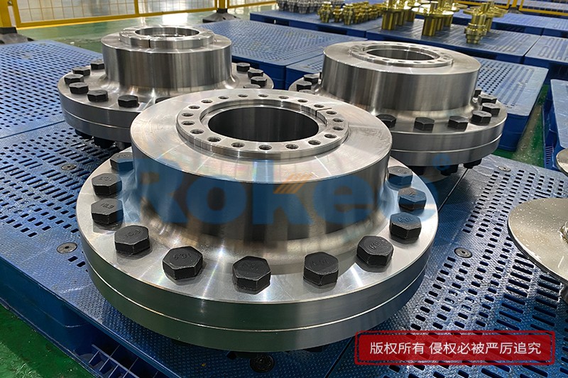
Rokee® is Flange Couplings Supplier from China, Support Customization and Export, due to excellent quality, complete technical services and superior cost performance, Rokee® Flange Couplings have been serving more than 60 countries and regions in the world, effectively operating in many corners of the world.
Flange Coupling is the standard forms of couplings, which are most extensively used. Flange coupling is a sort of connector between turning chutes that have two arrangements of flanges. Flanges are fitted or provided at the end of shafts.
-
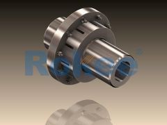
LMD Plum-shaped Flexible Coupling
LMD Plum-shaped Flexible Coupling is added with transition connection, which eliminates the need of axially moving the semi-coupling when replacing the elastomer. -
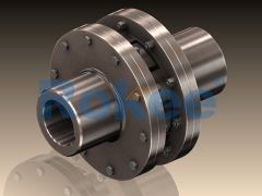
LMS Plum-shaped Flexible Coupling
LMS Plum-shaped Flexible Coupling adopts double transition flange connection, which eliminates the need of axially moving the semi-coupling when replacing the elastomer.
In the realm of mechanical power transmission, couplings serve as critical components that connect two rotating shafts, enabling the transfer of torque from a driver (such as an electric motor or internal combustion engine) to a driven machine (like a pump, compressor, or conveyor). Among the diverse types of couplings available, flange coupling stands out for its robustness, simplicity, and ability to handle high torque loads.
1. Definition and Core Function of Flange Coupling
A flange coupling is a type of rigid coupling that consists of two flanges—one attached to each of the two shafts to be connected—and a set of fasteners (typically bolts or studs) that secure the two flanges together. Unlike flexible couplings, which can accommodate misalignment between shafts to some degree, flange couplings are designed for applications where shafts are aligned with high precision. The primary function of a flange coupling is to transmit torque efficiently from one shaft to another while maintaining a solid connection that prevents relative motion between the shafts during operation.
Beyond torque transmission, flange couplings also serve to provide a stable and secure joint that minimizes vibration and ensures the smooth operation of the connected machinery. By creating a rigid link between the driver and driven shafts, they help to maintain consistent rotational speed and reduce the risk of mechanical failure due to misalignment or slippage. This rigidity, however, means that flange couplings require careful installation to ensure proper shaft alignment, as any misalignment can lead to excessive stress on the coupling components, bearings, and other parts of the mechanical system.
2. Design and Structural Components
The design of a flange coupling is relatively straightforward, yet it is engineered to withstand the demands of high-torque applications. The key structural components of a typical flange coupling include the following:
2.1 Flange Plates
The flange plates are the central components of the coupling, serving as the interface between the two shafts. Each flange plate is designed to be mounted on the end of a shaft, usually via a keyway and key, which prevents relative rotation between the flange and the shaft. The keyway is a slot cut into both the shaft and the flange hub, and the key is a rectangular or square piece of metal that fits into this slot, transferring torque from the shaft to the flange. Alternatively, some flange couplings may use a interference fit (press fit) to attach the flange to the shaft, eliminating the need for a keyway.
Flange plates are typically circular in shape, with a hub (the central portion that fits over the shaft) and a flange face (the flat, circular surface that mates with the other flange plate). The flange face may be smooth or have grooves to facilitate the distribution of lubricant, which helps to reduce friction and wear between the mating surfaces. The size and thickness of the flange plates are determined by the torque requirements of the application, with larger and thicker flanges used for higher torque loads.
2.2 Fasteners
Fasteners, such as bolts, studs, and nuts, are used to clamp the two flange plates together. The number and size of the fasteners are carefully selected to ensure that the coupling can transmit the required torque without slipping or failing. The fasteners are typically evenly spaced around the circumference of the flange plates to distribute the clamping force uniformly, which helps to maintain a tight and stable joint.
In some high-torque applications, the fasteners may be preloaded to enhance the clamping force and prevent loosening during operation. Lock washers or thread-locking compounds may also be used to secure the fasteners, especially in applications where vibration is a concern. It is crucial that the fasteners are made from high-strength materials that can withstand the tensile forces generated during torque transmission.
2.3 Gasket or Seal (Optional)
While not always present, some flange couplings may include a gasket or seal between the two flange faces. The purpose of this component is to prevent the ingress of dirt, dust, moisture, or other contaminants into the coupling, which can cause corrosion and wear. Gaskets are typically made from flexible materials such as rubber, cork, or compressed fiber, which can conform to the surface irregularities of the flange faces and create a tight seal.
3. Working Principle of Flange Coupling
The working principle of a flange coupling is based on the transfer of torque through a rigid connection between two shafts. Here is a step-by-step breakdown of how it operates:
1. Installation: Each flange plate is first mounted on the end of a respective shaft. This is typically done by sliding the hub of the flange over the shaft and securing it with a key (and sometimes a setscrew or nut) to ensure that the flange rotates in unison with the shaft.
2. Alignment: The two shafts are carefully aligned to ensure that their axes are collinear (i.e., along the same straight line). This is a critical step because any misalignment (radial, angular, or axial) will create additional stress on the coupling, bearings, and shafts, leading to premature failure.
3. Coupling Assembly: Once the shafts are aligned, the two flange plates are brought together so that their mating faces are in full contact. Fasteners (bolts or studs) are then inserted through the holes in the flange plates and tightened to clamp the two flanges securely together.
4. Torque Transmission: When the driver shaft rotates, it transfers torque to the attached flange plate via the keyway and key. The clamped fasteners then transmit this torque from the driver-side flange plate to the driven-side flange plate, which in turn rotates the driven shaft. The rigid connection between the flanges ensures that the rotational speed of the driven shaft matches that of the driver shaft, with minimal slip or vibration.
4. Common Types of Flange Coupling
While all flange couplings share the basic design of two flanges connected by fasteners, there are several variations tailored to specific applications and requirements. The most common types include:
4.1 Unprotected Flange Coupling
The unprotected flange coupling is the simplest and most basic type. It consists of two plain flange plates with a hub, keyway, and bolt holes. The flanges are connected directly, and there is no protective cover around the fasteners or the coupling joint. This type of coupling is typically used in low-speed, low-vibration applications where the coupling is not exposed to potential damage from external objects or where safety is not a major concern (e.g., in some industrial machinery where the coupling is enclosed within a housing).
One of the main advantages of unprotected flange coupling is its simplicity and low cost. However, its lack of a protective cover makes it unsuitable for applications where personnel may come into contact with the rotating coupling, as the exposed fasteners and rotating parts pose a safety hazard.
4.2 Protected Flange Coupling
To address the safety concerns of unprotected flange couplings, protected flange couplings feature a protective cover (or shroud) that encloses the fasteners and the mating faces of the flanges. This cover is typically integral to one of the flange plates or is a separate component that is attached to the flanges. The protective cover prevents personnel from accidentally coming into contact with the rotating parts and also helps to keep contaminants out of the coupling joint.
Protected flange couplings are widely used in applications where the coupling is exposed, such as in conveyor systems, pumps, and fans. They offer the same rigidity and torque-transmitting capabilities as unprotected couplings but with an added layer of safety.
4.3 Marine Flange Coupling
Marine flange coupling is a heavy-duty type designed specifically for use in marine applications, such as connecting the engine of a ship to its propeller shaft. These couplings are engineered to withstand the high torque loads and harsh environmental conditions encountered in marine environments, including saltwater corrosion, vibration, and shock loads.
Marine flange couplings typically have thicker flange plates and larger, high-strength fasteners to handle the extreme torque requirements. They may also include special seals or gaskets to prevent saltwater from entering the coupling joint and causing corrosion. Additionally, the flanges are often made from corrosion-resistant materials such as stainless steel or bronze.
4.4 Split Flange Coupling
Split flange coupling (also known as split-sleeve flange coupling) is designed to simplify installation and removal, especially in applications where the shafts are already in place and cannot be easily moved. Unlike solid flange couplings, which require the flange to be slid onto the end of the shaft, split flange couplings consist of two halves that can be clamped around the shaft without removing the shaft from the machinery.
The split design allows for easy maintenance and replacement of the coupling without disassembling the entire drive system. This type of coupling is commonly used in large industrial machinery, such as turbines, compressors, and large pumps, where downtime for maintenance needs to be minimized.
5. Applications of Flange Coupling
Flange coupling is widely used across a variety of industries due to its ability to transmit high torque, maintain rigidity, and provide a secure connection. Some of the key application areas include:
5.1 Industrial Machinery
In industrial settings, flange couplings are commonly used to connect electric motors to pumps, compressors, fans, conveyors, and mixers. These applications require a reliable torque transfer mechanism that can handle the high loads and continuous operation typical of industrial machinery. For example, in a manufacturing plant, a flange coupling may connect a motor to a conveyor belt system, ensuring that the conveyor operates at a consistent speed to move materials efficiently.
5.2 Marine Industry
As mentioned earlier, marine flange couplings are essential components in ships and boats, connecting the engine to the propeller shaft. The high torque generated by marine engines requires a robust coupling that can withstand the harsh marine environment, including saltwater corrosion and vibration. Flange couplings in marine applications are also designed to handle the shock loads that occur during ship operation, such as when the propeller hits debris in the water.
5.3 Power Generation
In power plants (both thermal and hydroelectric), flange couplings are used to connect turbines to generators. Turbines generate high torque at high speeds, and the coupling must transmit this torque efficiently to the generator to produce electricity. The rigidity of flange couplings ensures that the rotational speed of the turbine is accurately transferred to the generator, which is critical for maintaining the frequency and voltage of the electrical output.
5.4 Automotive Industry
While flexible couplings are more common in passenger vehicles, flange couplings are used in some heavy-duty automotive applications, such as trucks, buses, and construction equipment. They may be used to connect the transmission to the drive shaft or the drive shaft to the differential. In these applications, the coupling must handle the high torque generated by the engine and withstand the vibration and shock loads encountered during off-road or heavy-duty operation.
5.5 Mining and Construction
Mining and construction equipment, such as excavators, bulldozers, and crushers, require couplings that can handle extreme torque and harsh operating conditions. Flange couplings are used in these applications to connect engines to hydraulic pumps, gearboxes, and other components. The robustness of flange couplings makes them ideal for withstanding the dust, dirt, and shock loads common in mining and construction sites.
6. Key Considerations for Selecting Flange Coupling
Selecting the right flange coupling for a specific application is crucial to ensure optimal performance, reliability, and longevity. The following factors should be taken into account during the selection process:
6.1 Torque Requirement
The primary factor to consider is the torque that the coupling will need to transmit. The coupling must be rated to handle the maximum torque generated by the driver shaft, as well as any peak torque that may occur during operation (e.g., during startup or when the driven machine is under heavy load). Selecting a coupling with a torque rating lower than the required value will result in premature failure.
6.2 Shaft Size and Alignment
The coupling must be compatible with the diameter of the shafts being connected. Flange couplings are available in a range of hub sizes to fit different shaft diameters. Additionally, since flange couplings are rigid, the shafts must be aligned with high precision. If the application involves any potential misalignment (e.g., due to thermal expansion or vibration), a flexible coupling may be a more suitable choice.
Operating Speed
The operating speed of the shafts (measured in revolutions per minute, RPM) is another important consideration. At high speeds, centrifugal forces can act on the coupling components, leading to vibration and potential failure. Flange couplings designed for high-speed applications are typically balanced to minimize vibration and ensure smooth operation.
Environmental Conditions
The environmental conditions in which the coupling will operate can affect its performance and lifespan. Factors such as temperature, humidity, exposure to corrosive substances (e.g., saltwater, chemicals), and the presence of dust or debris should be considered. For example, in corrosive environments, couplings made from corrosion-resistant materials (such as stainless steel) or with protective coatings should be selected.
Installation and Maintenance Access
The ease of installation and maintenance should also be considered, especially in applications where downtime is costly. Split flange couplings are ideal for applications where the shafts cannot be easily removed, as they can be installed without disassembling the drive system. Additionally, couplings with accessible fasteners and simple designs are easier to maintain and repair.
7. Maintenance Practices for Flange Coupling
Proper maintenance is essential to ensure the longevity and reliable performance of flange couplings. The following maintenance practices are recommended:
7.1 Regular Inspection
Flange couplings should be inspected regularly to check for signs of wear, damage, or loosening. During inspection, the following should be checked:
- Fasteners: Ensure that bolts or studs are tight and not damaged. Loose fasteners can lead to slippage and excessive vibration.
- Flange Faces: Check for signs of wear, corrosion, or damage to the mating surfaces. Uneven wear or corrosion can affect the clamping force and torque transmission.
- Key and Keyway: Inspect the key and keyway for wear or deformation. A worn key can cause slippage between the flange and the shaft, reducing torque transmission efficiency.
- Seals/Gaskets (if present): Check for leaks or damage to the seals, which can allow contaminants to enter the coupling.
7.2 Lubrication
While flange couplings are generally dry-running, some may require lubrication of the mating faces or the keyway to reduce friction and wear. The type and frequency of lubrication depend on the application and the material of the coupling components. It is important to use the recommended lubricant and avoid over-lubrication, which can attract dust and debris.
7.3 Shaft Alignment Checks
Over time, shaft alignment can shift due to factors such as thermal expansion, vibration, or wear of the machinery. Regular alignment checks are necessary to ensure that the shafts remain collinear. Misalignment can cause excessive stress on the coupling, bearings, and shafts, leading to premature failure. Alignment can be checked using tools such as dial indicators or laser alignment systems.
7.4 Replacement of Worn Components
Any worn or damaged components (such as fasteners, keys, flanges, or seals) should be replaced promptly to prevent further damage to the coupling or the connected machinery. When replacing components, it is important to use parts that are compatible with the original coupling design to ensure proper fit and performance.
7.5 Cleaning
Keeping the coupling clean is essential to prevent the buildup of dust, dirt, or corrosive substances. Regular cleaning of the flange faces, fasteners, and protective cover (if present) helps to maintain the integrity of the coupling and reduce the risk of corrosion and wear.
8. Advantages and Disadvantages of Flange Coupling
Like any mechanical component, flange coupling has its own set of advantages and disadvantages, which should be considered when selecting a coupling for a specific application.
8.1 Advantages
- High Torque Capacity: Flange couplings are capable of transmitting high torque loads, making them suitable for heavy-duty applications.
- Rigidity: The rigid connection ensures that the driven shaft rotates at the same speed as the driver shaft, with minimal slip or vibration.
- Simplicity: The design is simple, which makes installation, maintenance, and repair relatively easy.
- Cost-Effective: Unprotected flange couplings are relatively inexpensive compared to other types of high-torque couplings.
- Durability: When properly maintained, flange couplings are durable and can withstand harsh operating conditions.
8.2 Disadvantages
- No Misalignment Compensation: Flange couplings cannot accommodate any misalignment between shafts. Improper alignment can lead to premature failure of the coupling, bearings, or shafts.
- Safety Hazard (Unprotected Type): Exposed rotating parts in unprotected flange couplings pose a safety risk to personnel.
- Requires Precise Installation: Proper shaft alignment is critical, which requires specialized tools and skilled labor.
- Vibration Transmission: The rigid connection can transmit vibration from the driver shaft to the driven shaft, which may affect the performance of sensitive machinery.
9. Conclusion
Flange coupling is a vital component in mechanical power transmission systems, offering a robust and efficient means of connecting two rotating shafts. Its simple design, high torque capacity, and durability make it a preferred choice in a wide range of industries, including industrial manufacturing, marine, power generation, automotive, and mining. By understanding the design, working principle, types, applications, selection criteria, and maintenance practices of flange coupling, engineers and maintenance professionals can ensure that the coupling is properly selected and maintained, maximizing the reliability and lifespan of the entire drive system.
While flange coupling has limitations, such as its inability to compensate for shaft misalignment, its advantages outweigh these drawbacks in applications where precise alignment is achievable and high torque transmission is required. As technology advances, improvements in materials and manufacturing processes continue to enhance the performance and durability of flange couplings, making them an even more valuable component in modern mechanical systems.
« Flange Couplings » Post Date: 2023/9/1
URL: https://www.rokeecoupling.com/en/tags/flange-couplings.html
- 2025-06-27Bush Pin Type Flange Couplings
- 2023-10-28Custom Double Diaphragm Flange Coupling
- 2023-10-28Cheaper Diaphragm Flange Couplings
- 2023-10-28Diaphragm Flange Coupling Types
- 2023-10-28Diaphragm Flange Coupling Supplier
- 2023-10-28Diaphragm Flange Coupling For Sale
- 2023-10-28Diaphragm Flange Coupling Accessories
- 2023-10-28Custom Diaphragm Flange Coupling
- 2023-10-28Diaphragm Flange Coupling Advantages
- 2023-10-28Single Diaphragm Flange Couplings
- 2023-10-24Pin Flange Coupling
- 2023-10-20Gear Flange Coupling
- 2023-10-12Diaphragm Flange Coupling Manufacturer
- 2023-10-12Diaphragm Flange Coupling Specification
- 2023-10-12Cross Universal Flange Couplings
- 2023-10-11Harvester Tyre Flange Couplings
- 2023-10-10Diaphragm Flange Coupling Price
- 2023-10-08Diaphragm Flange Couplings
- 2023-10-07Double Diaphragm Flange Coupling
- 2023-09-22Rectangular Toothed Flange Coupling
- 2023-08-24Manufacturer Of Single Diaphragm Flange Coupling